Aircraft systems
Flight controls
Although flight controls do not have big specificities compared to other aircraft, butterfly tail imposes a special operation. Both pitch input from the stick and yaw input from the rudder are combined to create the ruddervator movement.
However, this is transparent for the user and will use the flight stick as you would do on any other plane.
Servo assistance
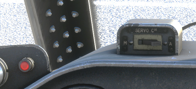
Aileron movement is assisted by servo, supplied by the hydraulic circuit. It can be disconnected by the pilot. As it is only an assistance aiming at easing aileron motion, servo effect has not been implemented in our aircraft.
A light will be visible when servo is disconnected.
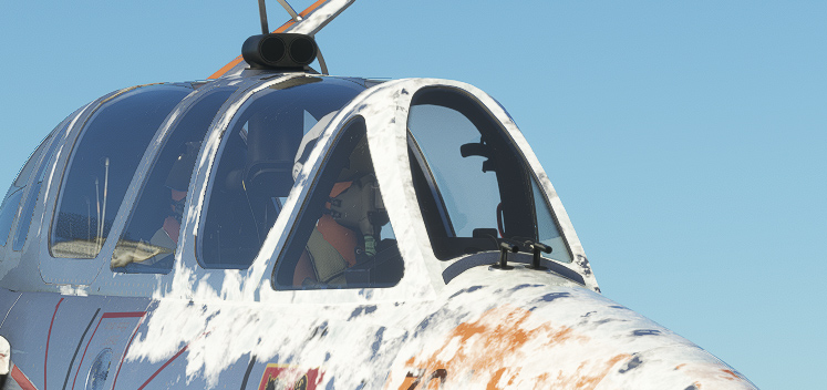
Canopy and pressurization
Pilot and copilot canopies can be handled separately.
You can lock and unlock canopy from the handle. A red light will be visible as soon as one of the canopies is not locked.
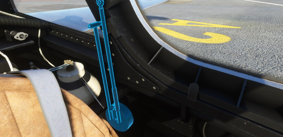
To open or close the canopy, you have to click on its left arm.
Cabin pressurization and air conditioning is functional as soon as canopy is locked. A multi-position switch allows to choose air conditioning type:
-
Closed (no air conditioning).
-
Pressurization (temperature selection on three positions).
-
Defrost (temperature selection on three positions).
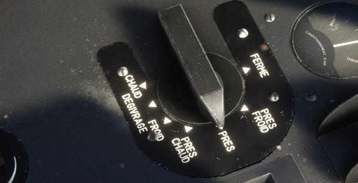
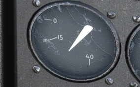
Current selected temperature can be seen on the gauge.
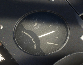
When defrost is selected, air is directed upon the windshield. In addition, defrost handle on the main panel allows to spurt alcohol on the front glass to help defrosting (action is not simulated).
Electrical system
Electric supply is provided in flight, thanks to a generator, rated 28.5V, connected to the left engine.
A converter allows to feed gyroscopes.
Lights
The Fouga is fully capable of night flying, and each light has been reproduced in the game.
In the exterior, you will find a landing light and navigation lights.
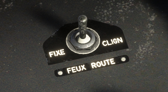
Navigation lights can be set on three positions:
-
OFF
-
FIXED
-
FLASHING, where lights will blink approximately one time per second.
As we have to manage three distinct position, keyboard input cannot be taken into account. You need to use the switch on the left console to turn on or off the navigation lights.
In the interior, you will find for pilot and copilot:
-
Console lights (white).
-
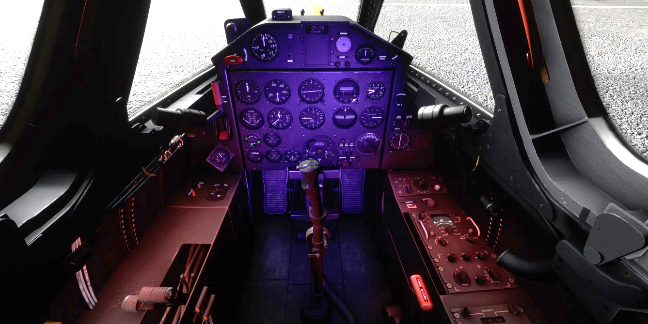
UV lights (front panel lights set by potentiometer).
-
Emergency lights (red console lights set by potentiometer).
-
Radio light (backlight for radio panels).
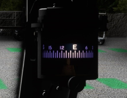
Pilot also has a compass light:
Fuses
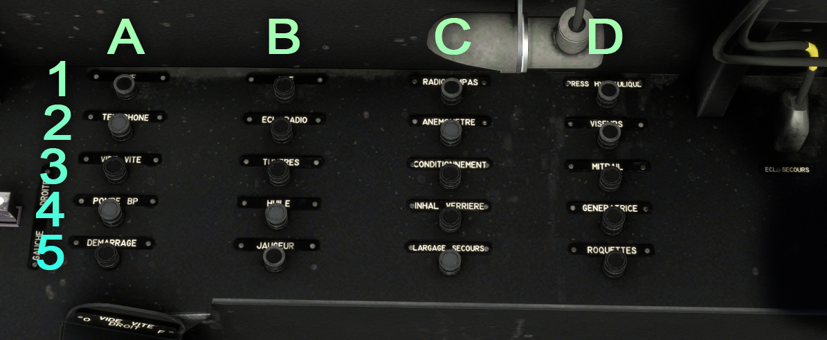
| # | Description | # | Description |
|---|---|---|---|
| A1 | VHF | C1 | Radio compass |
| A2 | Intercom | C2 | Pitot heat |
| A3 | Fuel dump | C3 | Air conditioning |
| A4 | Low pressure fuel pump | C4 | Low oxygen and canopy lights |
| A5 | Starter | C5 | Emergency drop |
| B1 | UHF | D1 | Hydraulic pressure indicator |
| B2 | Radio lights | D2 | Gun sight |
| B3 | Nozzle temperature indicator | D3 | Gun |
| B4 | Oil pressure and temperature indicators | D4 | Alternator |
| B5 | Fuel level indicator | D5 | Rockets |
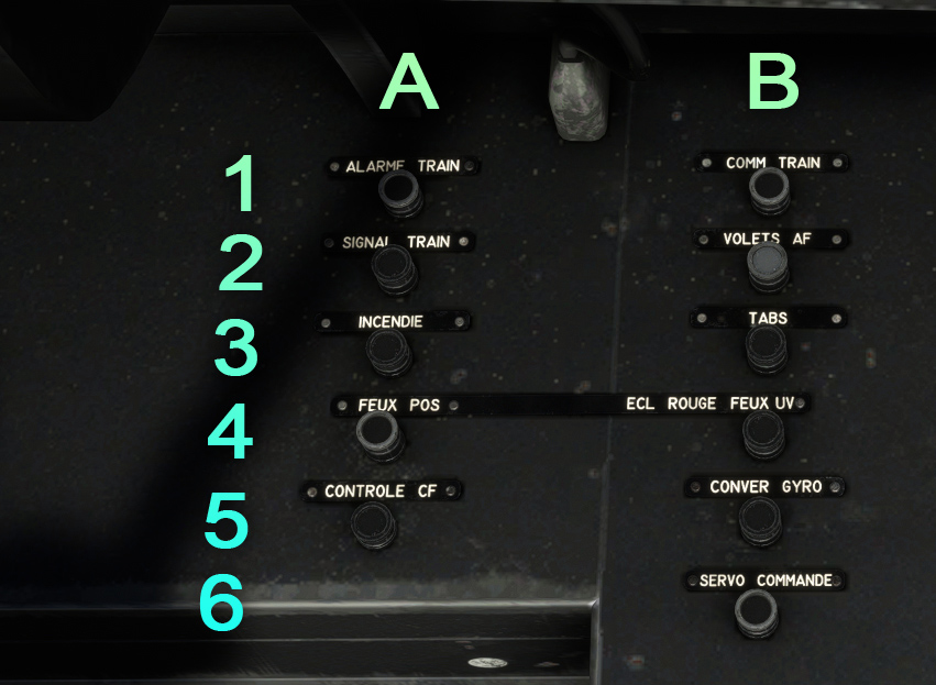
| # | Description | # | Description |
|---|---|---|---|
| A1 | Landing gear alarm light | B1 | Landing gear |
| A2 | Landing gear lights | B2 | Flaps and spoilers |
| A3 | Fire alarm lights | B3 | Tabs |
| A4 | Navigation lights | B4 | Red and UV lights |
| A5 | Turn coordinator | B5 | Gyros |
| B6 | Servo |
Fuel system
The Fouga has three fuel tanks:
-
One fuselage tank (divided in two parts) containing 730 liters.
-
One tank on left wing tip (125 liters).
-
One tank on right wing tip (125 liters).
On some versions, bigger tip tanks (each 230 liters) can be installed. They are not implemented in our version yet.
In addition to those tanks, there is a back flying accumulator (11 liters) allowing to feed the engines when the aircraft is flying inverted. After approximately 30 seconds, engines will lose power and you will need to bounce back to resume fuel supply.
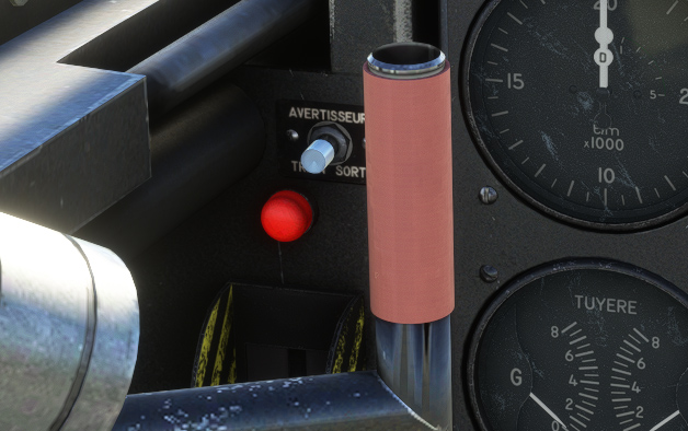
A low-pressure electric fuel pump is connected to the main electric circuit, allowing to feed high-pressure pumps and the back flying accumulator.
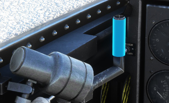
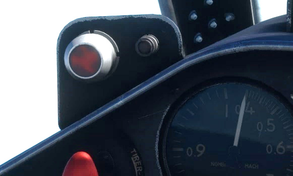
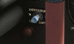
When fuel pressure goes below 350 millibars (too low to fill back flying accumulator) a red light will glow on the left of the panel:
Hydraulic system
The Fouga is fitted with two hydraulic circuits, one NORMAL circuit and an EMERGENCY circuit. A pump connected to the left engine allows to maintain a 250 bars pressure into the circuit.
The following systems are connected to the hydraulic circuit:
-
Landing gear.
-
Flaps.
-
Brakes.
-
Spoilers.
-
Aileron servo.
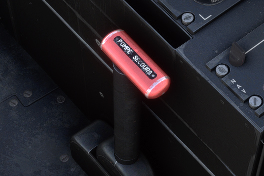
Emergency circuit is supplied thanks to the handle on the right of the pilot.
Landing gear
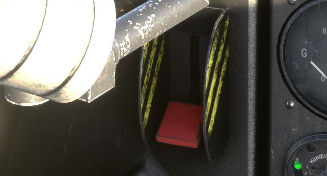
Equipped with a tricycle landing gear, the movement is managed with the red handle on the left of the main panel.
Nose gear has a free movement and is not connected to the rudder pedals. During taxi, turns are done using differential braking. As differential braking can be achieved with specific hardware only (rudder pedals with brakes), we chose to connect front wheel to the rudder to facilitate ground manoeuvres.
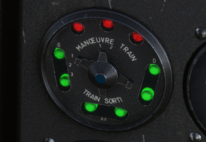
A gauge with several bulbs allows to control landing gear state:
-
3 red bulbs are turned on when landing gear is not locked (not fully open or not fully retracted).
-
Two sets of 3 green bulbs are turned on when landing gear is expanded and locked.
A light above main panel will blink when one of the engines is below 15,000 RPM and the landing gear is not down.
In case of issues with lights, you can use the auditory check button. Once pressed, a continuous sound will be emitted if landing gear is down and locked.
Flaps
The CM.170 has trailing edge flaps, composed of two elements per wing.
Thanks to the switch on the left console, flaps can be set on any position between 0 and 40 degrees. You can still assign pre-assign takeoff (15 degrees) and landing (40 degrees) positions to any of your joystick button to facilitate its use.
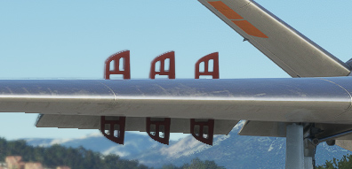
Spoilers
The aircraft has six plates per wing, each of them can rotate between 0 and 90 degrees.
Spoiler switch is present on the right side of the throttle, for both pilot and copilot. Like flaps, it is a three positions switch.
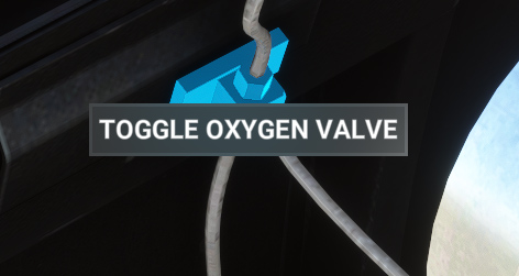
Oxygen
Oxygen bottles are located behind the pilot seat. With a 2000 litres capacity (initial pressure of 150 bars), system can be opened or closed from a valve on the right of the pilot.
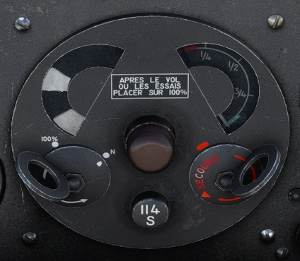
Both pilot and copilot have an oxygen regulator with:
-
Needle showing the remaining oxygen in the circuit.
-
Blinker which should do a complete movement for each breathing in and breathing out of the pilot/copilot.
-
Bulb which will light up when oxygen pressure drops below 25 bars.
-
Switch (N – 100%) to provide pure oxygen.
-
Switch (N – Secours) used in case of emergency to provide pure oxygen in overpressure (50 mbar).
Pure oxygen is automatically supplied above 34,000 ft.
Autonomy will depend on the cabin altitude, and can be read in the following table (in hours):
| Cabin altitude (ft) | Oxygen regulator | 2000 L (FULL) | 1500 L (3/4) | 1000 L (1/2) | 500 L (1/4) |
|---|---|---|---|---|---|
| 30,000 | N | 5.2 | 3.9 | 2.6 | 1.3 |
| 30,000 | 100% | 5.2 | 3.9 | 2.6 | 1.3 |
| 25,000 | N | 5.2 | 3.9 | 2.6 | 1.3 |
| 25,000 | 100% | 4 | 3 | 2 | 1 |
| 20,000 | N | 5.2 | 3.9 | 2.6 | 1.3 |
| 20,000 | 100% | 3.2 | 2.4 | 1.6 | 0.8 |
| 15,000 | N | 5.2 | 3.9 | 2.6 | 1.3 |
| 15,000 | 100% | 2.5 | 1.8 | 1.2 | 0.6 |
| 10,000 | N | 5.2 | 3.9 | 2.6 | 1.3 |
| 10,000 | 100% | 2 | 1.5 | 1 | 0.5 |
| 0 | N | 7 | 5.2 | 3.5 | 1.7 |
| 0 | 100% | 1.4 | 1 | 0.7 | 0.3 |
Radio
The right console is dedicated to everything related to the radios:
-
UHF panel (COM 1).
-
Radio compass (ADF) panel.
-
Sound mixing panel (intercom).
-
VOR panel (NAV 1).
Sound mixing panel is inoperative as COM and NAV volumes are already adjustable from UHF and VOR panels.
UHF panel
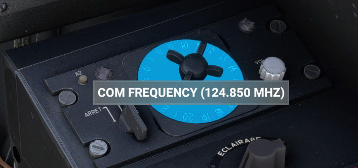
Originally, UHF box has pre-registered frequencies that can be set before flight and selected with the 20 positions wheel.
In order to be usable in the simulator, you can select any COM frequency from the central wheel.
Left knob allows to turn on/off UHF (HOM position is inoperative).
Right knob allows to set COM 1 volume.
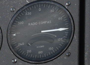
Radio compass
In the CM.170, radio compass panel has plenty of knobs and switches used to connect manually to a station.
This complex operation is not needed to connect to modern NDB transmitters, and thus was not simulated in our aircraft.
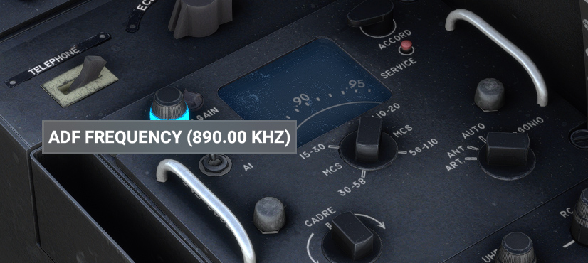
You can simply use the top left knob in order to change ADF frequency.
ADF indicator will point to station direction.
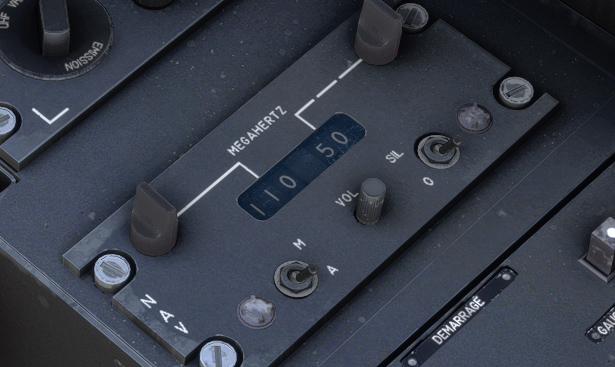
VOR panel
This panel allows to select NAV frequency, thanks to two knobs.
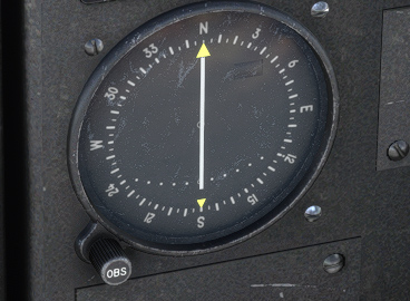
The course deviation indicator shows deviation from the radial that can be set with OBS knob.
The CM.170 is not equipped with ILS.