Aircraft systems
Flight controls
Roll and pitch axis are all directly driven from the yoke, mechanically and without any hydraulic assistance.
Side movement of the stick handgrip through the control linkage of roll ensures a deflection of the ailerons by 13 degrees downwards and 18 degrees upwards. Ailerons are statically overbalanced (110 %) by integrated balance weights.
Longitudinal movement of the stick ensures a deflection of the elevator between 20 degrees (nose up) and 1° degrees (nose down). Static balance (100%) is performed with weights located in the horn of each tip and in the leading edge. Return to neutral position is performed thanks to a spring bellcrank.
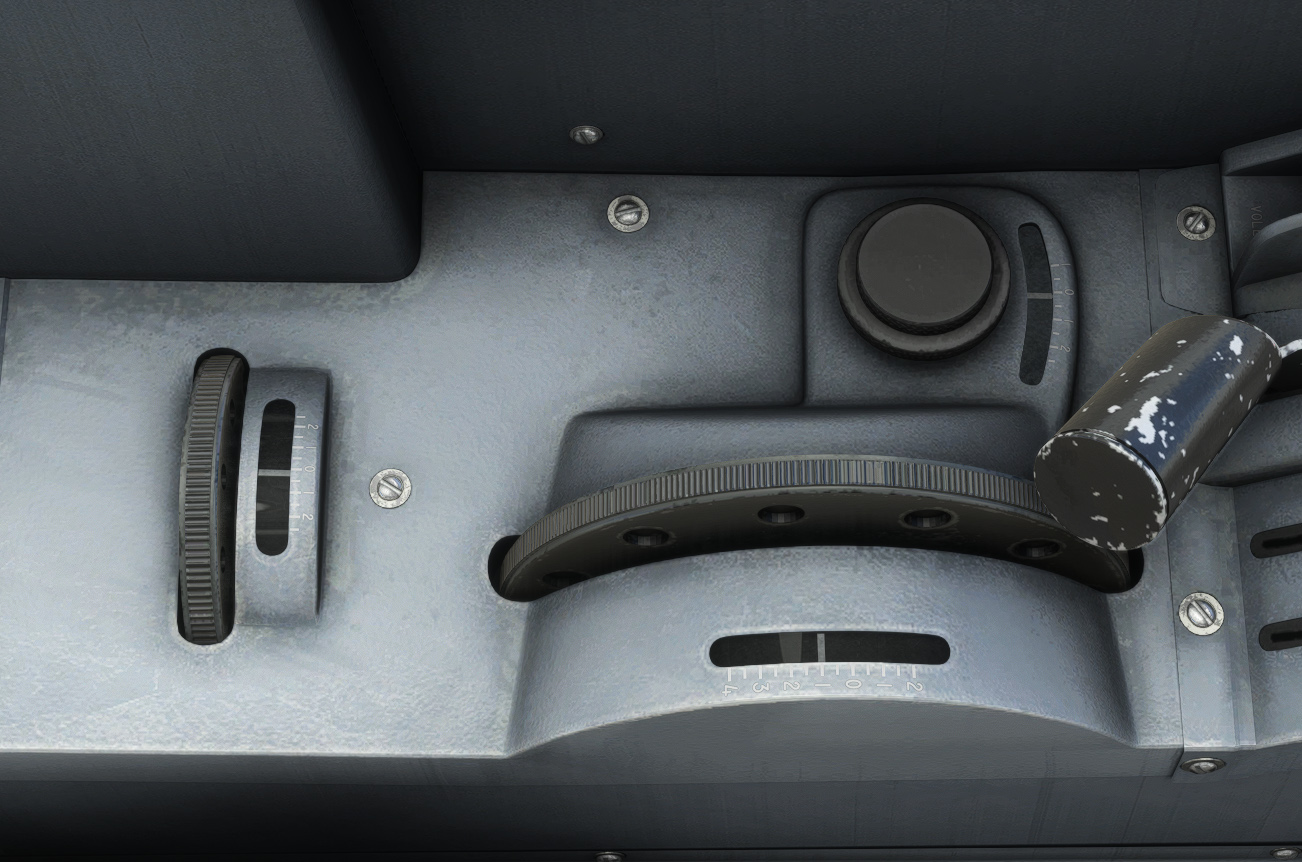
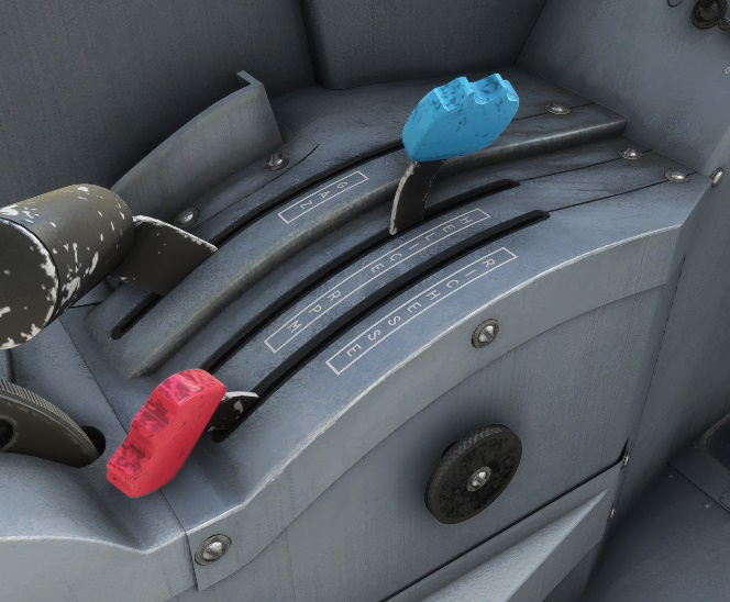
The aircraft can be compensated on three axes thanks to the trim wheels located on the left panel:
-
+ 4° / − 2° on pitch axis.
-
+ 2.5° / − 1° on yaw axis.
-
+ 2.5° / − 2.5 ° on roll axis.
Even if not fitted with an autopilot, those trims allow to reach a very good stability during cruise flight, in non-turbulent conditions.
Rudder control is actuated through a pressure on left and right pedals, and braking is ensured through a pressure on upper part of each pedal. Nose wheel is of free castor type (free wheel not linked to rudder pedals). Unfortunately, MSFS does not currently allows faithfully replication of free castoring wheels, so you will see the nose wheel move depending on rudder input.
Canopy
Front and rear canopies are made of plexiglass convex panels mounted in a metallic frame. The assembly moves on two rails thanks to four rollers for the front canopy and six rollers for the rear canopy.
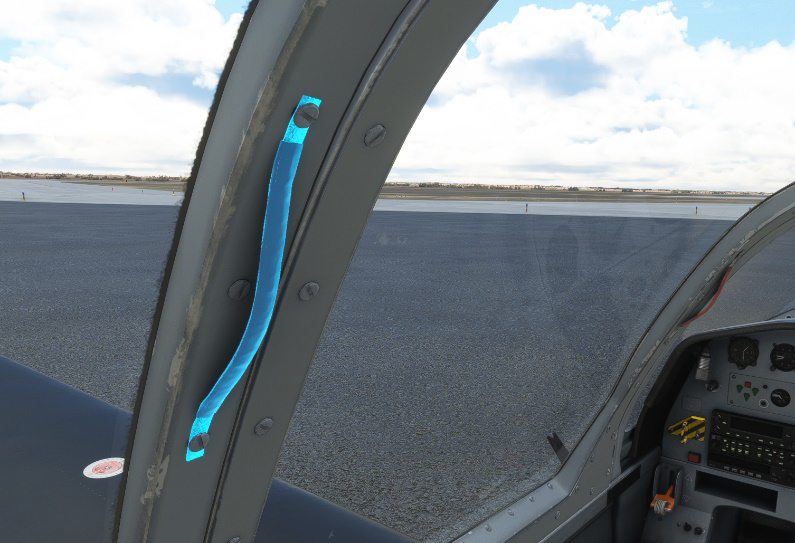
Two internal handles are installed on the forward former of each canopy. Two additional handles are installed on the central former of the rear canopy.
Front canopy locking against the windshield is performed by two side catches in which enters the windshield locking pins. The rear canopy locking against the front canopy is identical.
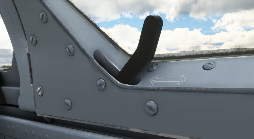
To open any of the two canopies, you first need to unlock it with the lock handle on the right, and then click on one of the two red handles to translate the canopy. You can achieve the same directly from the EFB.
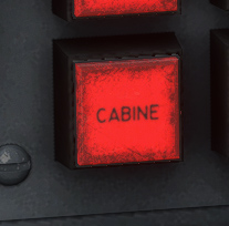
You can visualize any unlocked cabin with “CABINE” indicator light in the alarms panel.
Electrical system
The direct-current electrical power is supplied by a lead acid battery (24 V/17 Ah) associated with an engine-driven alternator. This alternator supplies a 28V D.C. voltage, nominal rating 70 A, after rectification.
Circuit breakers
Direct current supply is performed by 6 bus each protected by “Pull-Off” circuit breakers. Bus 4 is used by all avionics and bus 5 – 6 for rear station only.
Each circuit breaker is functional.
Front station circuit breakers
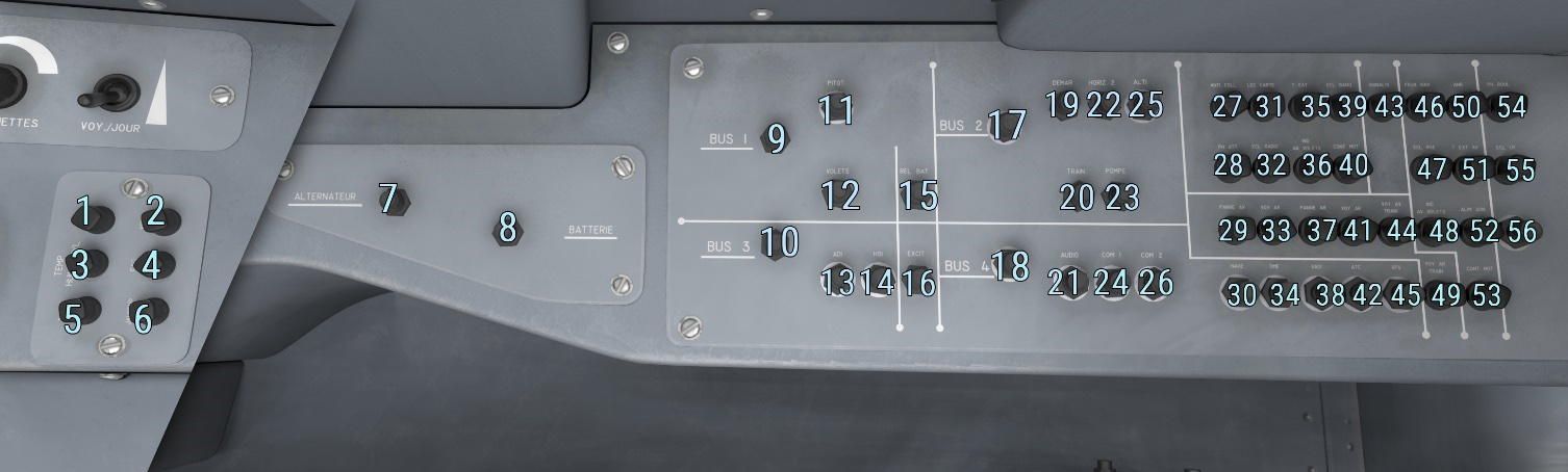
| # | Description | # | Description |
|---|---|---|---|
| 1 | Oil pressure gauge | 29 | Front station failure warning lights |
| 2 | Voltmeter gauge | 30 | GNC 255 radio navigation |
| 3 | Oil and cylinder temperature gauge | 31 | Front map reader |
| 4 | EGT gauge | 32 | Front station radio unit |
| 5 | Tachometer gauge | 33 | Front station panel indicator lights |
| 6 | Fuel level gauge | 34 | KN 62 DME transceiver |
| 7 | Alternator | 35 | Rear station temperature indicator |
| 8 | Battery | 36 | Rear station flap indicator |
| 9 | BUS 1 | 37 | Rear station failure warning lights |
| 10 | BUS 3 | 38 | GAD ARINC converter |
| 11 | Pitot heat | 39 | Front console lighting unit |
| 12 | Flap motor | 40 | Front station engine monitoring cluster (oil/cylinder temperature, EGT, tachometer) |
| 13 | Front station G5 PFD | 41 | Rear station panel indicator lights |
| 14 | Front station G5 HSI | 42 | GTX 335 transponder |
| 15 | Battery relay | 43 | Landing gear indicating power supply |
| 16 | Alternator excitation | 44 | Front station landing gear indicator lights |
| 17 | BUS 2 | 45 | GPS unit |
| 18 | BUS 4 | 46 | Navigation lights |
| 19 | Starter relay | 47 | Front station red lights |
| 20 | Landing gear | 48 | Front station flap indicator |
| 21 | GMA 340 audio panel | 49 | Rear station landing gear indicator lights |
| 22 | Attitude indicator gyro | 50 | Active noise reduction power supply |
| 23 | Electric fuel pump | 51 | Front station temperature indicator |
| 24 | GNS/GTN VHF transceiver | 52 | Warning sounds unit |
| 25 | Front and rear altimeter shakers | 53 | Front station engine monitoring cluster (fuel gauge, oil pressure, voltmeter) |
| 26 | GNC 255 VHF transceiver | 54 | Taxi light |
| 27 | Anti-collision light unit | 55 | Front station UV lights |
| 28 | Landing lights | 56 | USB socket power supply |
Rear station circuit brakers
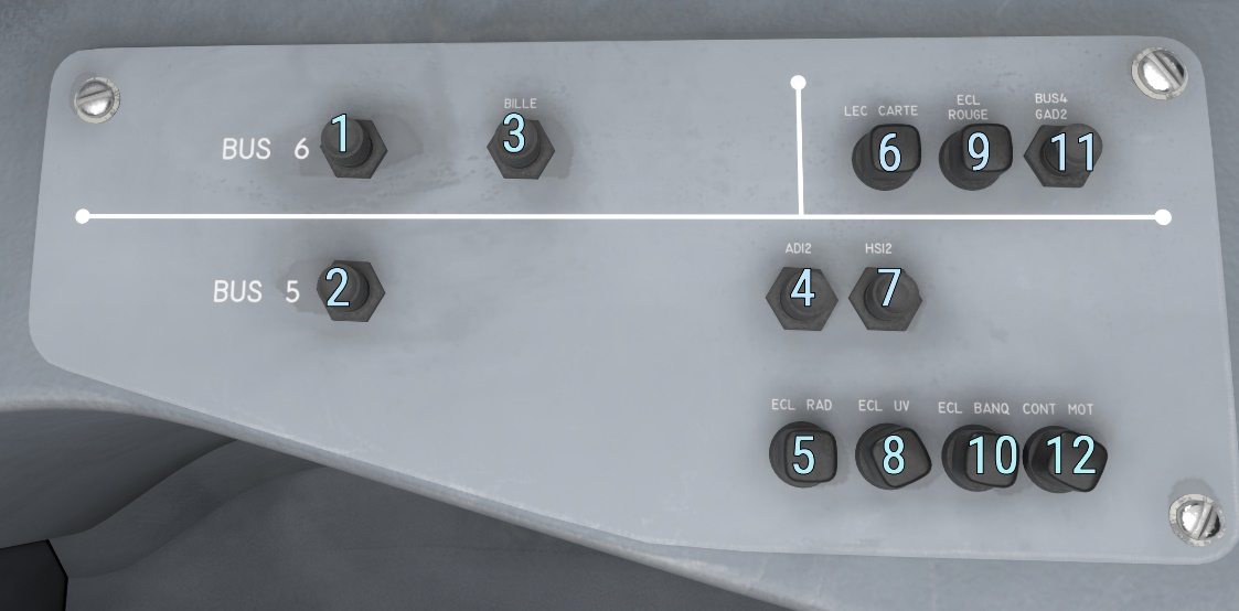
| # | Description | # | Description |
|---|---|---|---|
| 1 | BUS 6 | 7 | Rear station G5 HSI |
| 2 | BUS 5 | 8 | Rear station UV lights |
| 3 | Turn and bank indicator (not implemented) | 9 | Rear station red lights |
| 4 | Rear station G5 PFD | 10 | Rear console lighting unit |
| 5 | Radio lighting unit | 11 | GAD ARINC converter |
| 6 | Rear map reader | 12 | Engine monitoring cluster system + rear station voltmeter gauge |
Lights
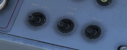
Exterior lights
The TB-30 is fitted with the following exterior lighting:
-
Navigation lights (“FEUX NAV”).
-
Strobe lights (“ANTI COLL”).
-
Taxi and landing lights.
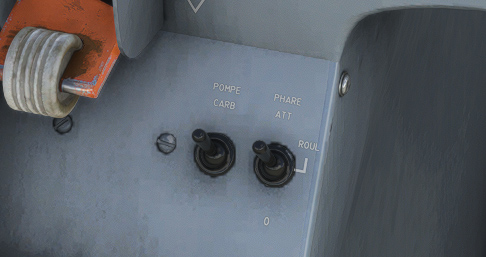
Strobes and navigation lights switches can be found on right console of front station only:
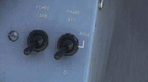
Taxi and landing lights are managed with a single switch on left console of front station. Taxi light is ON in middle position (“ROUL”) and landing light is ON in top position (“PHARE ATT”).
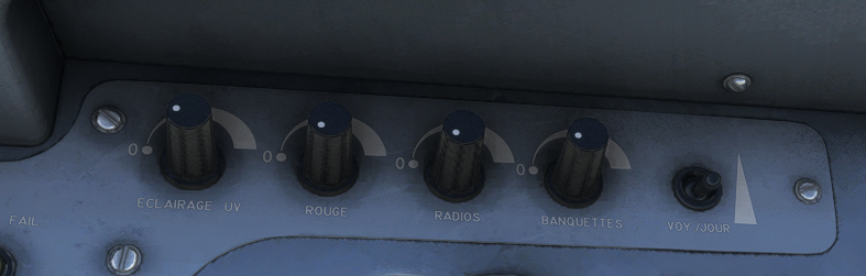
Interior lights
On each station, you will find five knobs controlling interior lights:
-
UV lights (“ECLAIRAGE UV”) on front panel.
-
Red lights (“ROUGE”) on front panel.
-
Radio lights (“RADIOS”) to set intensity of avionic units (knobs and buttons).
-
Console lights (“BANQUETTES”) for left and right consoles lights.
-
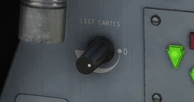
Map light (“LECT CARTES”) to use map reading light on the left of the panel.
Flaps
The aircraft has two wing flaps, that can be extended to any angle between 0 and 25 degrees.
The flaps are of single slot type, each of them being carried by arc shaped sliders (two per flap), which ensure a deflection and return effect.
An electrical motor is controlling a screw jack moving inside sliders to ensure flaps deflection.
You can choose to set them from your flight controller, or by using the switch placed on the left of throttle lever.
Current flaps position is reflected on the following gauge (front panel):
Fuel system
Fuel is contained in two tanks located in the wings leading edge (one per half-wing), feeding the engine through a feeder tank.
Pilot can switch between either left or right tank using a fuel selector located on front station only.
In the middle position, both tanks direct fuel towards feeder tank. However, this position may lead to transfer incidents and must not be used.
An inverted flight feeder tank which contains 2.5 litres allows a limited time of inverted flight. Rollover valves installed in each tank limit fuel waste through air vents during inverted flying. After approximately two minutes of inverted flying, fuel feeding will stop, resulting in engine shutdown.
A decanting filter is installed in the feeder tank outlet and is provided with a drain valve, easily accessible below the aircraft nose.
Electric fuel pump is installed just after the decanting filter and is controlled by a switch on the front station left console.
A 140 μm filter between electric pump and shut-off valve protects engine pump.
Shut-off valve is located behind firewall and can be operated from both front and rear station.
The mechanical pump is of vane-type, installed on the rear part of the engine and driven by the latter. It supplies fuel necessary to the injection system.
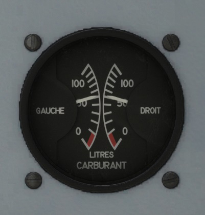
Fuel level is monitored on its dedicated gauge (front station). Measurement is achieved with two electrically transmitting gaging dipsticks for each tank.
Powerplant & Propeller
Engine
The aircraft is equipped with a six cylinders piston engine (Avco Lycoming type AEI0-540 L1B5D), rated 300 HP (224 kW) at 2700 rpm. Combustion is ensured by an injection system.
| Pistons | 6 |
| Cooling | Air-cooled |
| Configuration | Flat, opposed cylinders |
| Power (Max continuous) | 300 HP |
| Cubic capacity | 8.87 L |
| Compression ratio | 8.7 |
Air intake
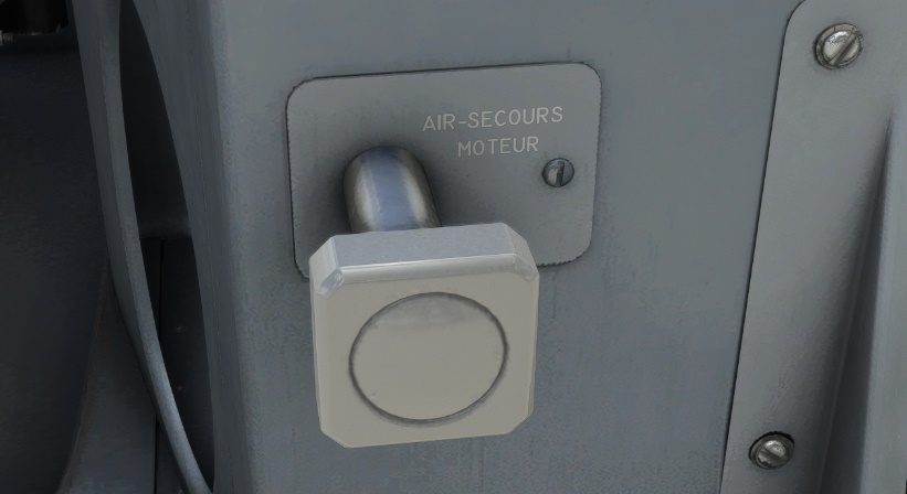
Air intake in ensured by a box equipped with a flap, which may close cool air inlet to let in hot air from the engine, in order to avoid icing risk of injection unit. This hot air is not filtered. The flap is controlled by the “AIR SECOURS MOTEUR” lever.
Mixture
An Automatic Mixture Controller (AMC) sets mixture permanently depending on ambient conditions to get the best power mixture (EGT peak − 70°C).
A fuel metering lever allow to adjust manually the mixture, when operation with a mixture near best power one is not wanted.
Ignition
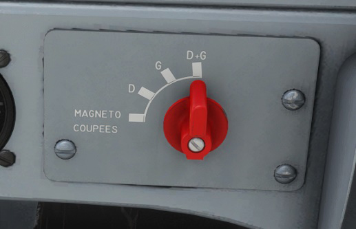
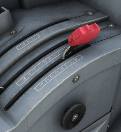
Ignition is performed through a dual magneto, which provides spark plugs with a high-voltage double ignition (two spark plugs per cylinder). Ignition order is 1-4-5-2-3-6.
A selector, located only at front station on instrument panel strip right hand side, allows magneto operation and selection.
Engine monitoring
Monitoring instruments are arranged on right hand instrument panel of each station. These instruments are:
-
A manifold pressure (mbar) and fuel flow (L/h) dual indicator.
-
An electrical tachymeter (tr/min).
-
An EGT indicator (°C).
-
An oil temperature and cylinder temperature dual indicator (°C).
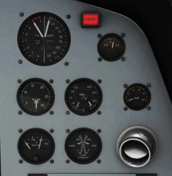 An oil pressure indicator (bars).
Propeller
The “Hartzell” metallic propeller is of pitch-regulated constant-speed type. It is a direct drive propeller and turns clockwise.
Propeller speed is dependent upon the balance between two actions:
-
Action of counterweights, tending to position the propeller in high pitch by propeller rotation.
-
Action of the governor, engine-driven and fed by lubrication system, tending to position the propeller in low pitch. Pilot acts on governor spring with the propeller control lever.
In case of regulation failure, pressure drop results in automatic transition to high pitch.
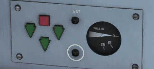
Landing gear
The retractable tricycle landing gear consists of a nose gear and two main gears. Each landing gear is of shock-compensating rocker-beam type and is equipped with an oil/air shock absorber and a single wheel provided with a low-pressure tire.
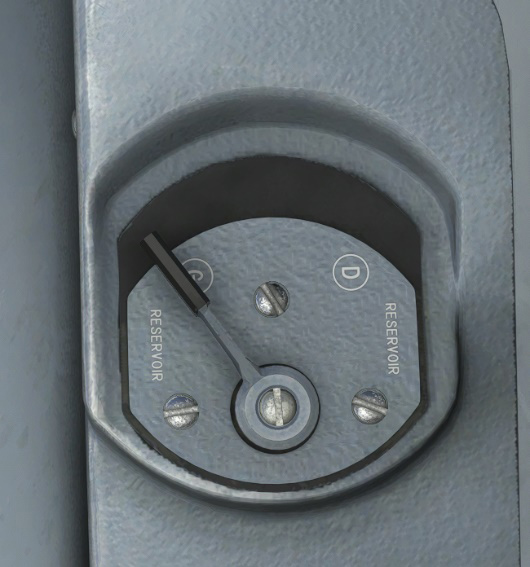
The landing gear wells are partially closed by doors the travel of which is mechanically linked to the landing gear maneuver. The landing gear is activated by hydraulic pressure provided by a dual direction gear electric pump and its tank.
Landing gear control lever is located on the left-hand side of the instrument panel at each pilot station, and has two positions. Interconnection between front and rear station is ensured by flexible controls. While aircraft is on ground, control lever is locked down by an electromagnetic lock. Control can be pushed up again only if:
-
Landing gear shock absorbers are extended.
-
Nose landing gear is in the centerline.
INDICATIONS
Current landing gear state is indicated on the following panel:
-
Red light is on when landing gear is not fully locked.
-
Green lights (one per gear) are on when landing gear is down and locked.
One button allows to test correct functioning of the lights. The other button will emit a radio signal (“BIP”) when pressed if landing gear is locked down.
To avoid any unvoluntary belly landing:
-
A red light on left hand side of main panel will blink when throttle is on idle position and landing gear is not extended.
-
An aural warning can be heard when flaps are extended to more than 20° and landing gear is not extended. It will not stop until flaps deflection is reduced or landing gear is put down.
Alarms
On each station you will find a panel dedicated to alarms on the bottom right part.
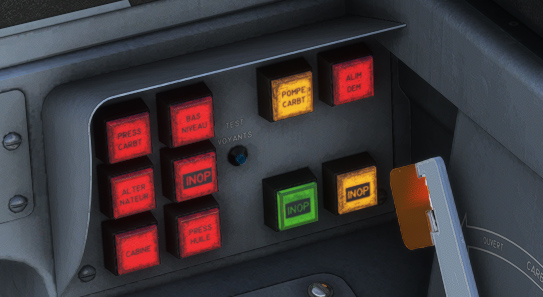
A button allows to test correct lighting of each alarm.
Depending on severity, different color lights are used:
-
Red for failures and important information.
-
Orange for simple indications.
A day/night switch allows to change light intensity used for all alarms.

Each red alarm can be clicked to disable its lighting up.
If at least one red alarm is active, the general red light on top of the panel will light up:
You will find same alarms on front and rear panel, with the following rules:
-
“PRESS CARBT” (fuel pressure): fuel pressure lower than 0.84 bar.
-
“BAS NIVEAU” (low fuel level): currently selected tank contains only 10 liters or below.
-
“ALTERNATEUR” (alternator): main bus voltage lower than 26 V.
-
“CABINE” (cabin): unlocked canopy.
-
“PRESS HUILE” (oil pressure): oil pressure lower than 1.75 bar.
-
“POMPE CARBT” (fuel pump): fuel pressure greater than 1.7 bar.
-
“ALIM DEM” (starter supply): starting knob being pushed, or stuck starter relay.