Avionics
Our TB-30 is based on civilian-converted models, retrofitted from military models used in French Air Force and retired from service. Differences are very minor, and avionics is the most noticeable difference you will find.
Military radios have been removed to be replaced by conventional civil communication and navigation units, described in this section.
VOR/ILS
Beside the numerous screens present on the aircraft, you will find a simple VOR/ILS indicator, that you can use as a course deviation indicator with glideslope indicator.
Course can be set from the knob on bottom left.
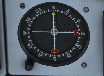
NAV source to use can be changed from the switch just below:
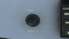
NAV 1 frequency is set from the GPS and NAV 2 frequency from the secondary radio unit.
G5 PFD & HSI
The two main screens you will find on front panel consist of:
-
A PFD (Primary Flight Display), displaying attitude information and principal flight parameters:
-
Airspeed.
-
Altitude, including a reference bug and current barometric reference.
-
Vertical speed.
-
Horizontal situation.
-
Slip and turn rate indicator.
-
Current heading, including a reference bug.
-
Ground speed.
-
Course deviation indication and glide slope pointer when there is an active radio station providing that information.
-
-
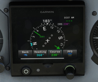
A secondary display with HSI (Horizontal Situation Indicator) displaying:
-
Current heading, including a reference bug.
-
Course deviation to active navigation source (coming from GPS or from radio station).
-
Distance to station.
-
Ground speed.
-
Each of them can be switched ON or OFF with the left button.
A knob allows to set barometric reference (unit can be changed from the menu), and can be clicked to navigate through the menus (left plus right click).
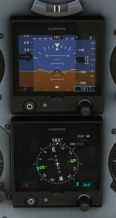
You can switch between VLOC and GPS mode from the GPS unit. In VLOC mode, NAV 1 source will be used.
Course selection is done from the GPS unit (OBS) in GPS mode. In VLOC mode, you can select course from the HSI menu.
You will not find 100% of functionalities compared to a real G5, however you already have essential ones.
GPS
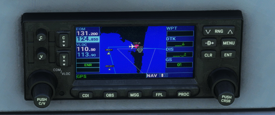
On the center bottom of the main panel, you will find a GPS unit, using Working Title GNS 430 by default.
This unit is managing COM 1 and NAV 1 frequencies.
PMS50 and TDS GTN integration
If you own PMS50 GTN or TDS GTNXi add-ons, you can easily use them on our aircraft instead of the default unit.
You only need to select GTN unit in the electronic flight bag (tablet) main page depending on which of both products is installed on your PC.
PMS50 GTN can be used on Xbox as well.
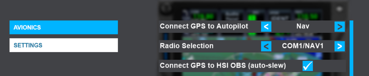
If you are using TDS implementation, please check in TDS GTNXi Flight Sim Interface that GTN650Xi Unit 1 is connected on COM1/NAV1:
GNC 255 Radio
While GPS unit manages main frequencies, an additional radio unit is used to set COM 2 and NAV 2 frequencies.
This GNC 255 radio is partially customized as the default one provided in the simulator only manages COM frequencies.
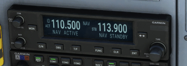
This unit provides following features:
-
Two knobs on the left:
-
Power On/Off, used for COM volume and Squelch On/Off.
-
NAV volume and NAV Ident On/Off.
-
-
Buttons:
-
“MON” to monitor active and standby frequencies.
-
“C/N” to switch between COM and NAV menus.
-
“OBS” to display deviation related to radio station (inoperative for now).
-
“T/F” to switch between To/From selection (inoperative for now).
-
“FUNC” to enter functions menu.
-
“CLR” to clear current selection.
-
“ENT” to enter selection.
-
Frequency swap key.
-
-
Double knob to adjust standby frequency.
GMA 340 Audio Panel
Audio panel is fully functional and is used to manage various audio channels.
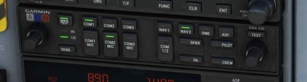
It features two double knobs to set pilot/copilot intercom volume and squelch level, and the following buttons:
-
“MKR” to mute or enable marker beacon sounds.
-
“SENS” to switch between HIGH and LOW marker beacon sensitivities.
-
Three buttons – “COM1”, “COM2”, “COM3” – to enable COM reception. Please note that there is no COM 3 channel of the aircraft.
-
Three buttons – “COM1 MIC”, “COM2 MIC”, “COM3 MIC” – to choose COM channel to use for transmission.
-
Four buttons – “NAV1”, “NAV2”, “DME”, “ADF” – for radio audio listening.
-
“COM 1/2" to split pilot and copilot communication on two channels.
-
“SPKR” for speaker function.
-
“PA” to broadcast pilot and copilot mic audio over the cabin speaker.
-
“PILOT” and “CREW” to manage crew or pilot audio isolation.
-
“TEST” to test all lights of the unit.
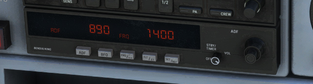
KR87 DME
A distance measuring equipment (DME) unit is placed below the audio panel.
As radio magnetic indicator (RMI) has been replaced by G5 display units in the civilian TB-30 we based our work on, it is not possible to retrieve distance and bearing to selected NDB, as the G5 only displays GPS, VOR and VLOC data.
DME unit is still useful and has been kept for its chronometer function.
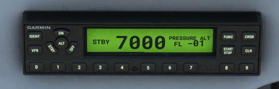
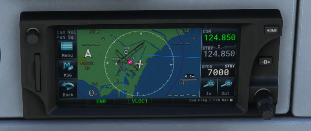
GTX 355 Transponder
Transponder is placed on bottom center of the panel.
It is the exact same model you will find in plenty other aircraft in the simulator.