Avionics
Our Bronco has been modeled with its original avionics only, except an optional GPS unit that you can use if needed. While the Bronco is not well suited for IFR flights, it has radio navigation capabilities (VOR, ADF, TACAN) and can perform ILS approaches.
COM/NAV
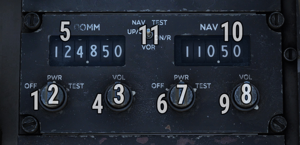
On right console, a COM/NAV panel allows to set COM1 and NAV1 frequencies.
| # | Description | # | Description |
|---|---|---|---|
| 1 | COM power knob | 7 | NAV frequency knob (units) |
| 2 | COM frequency knob (units) | 8 | NAV frequency knob (decimals) |
| 3 | COM frequency knob (decimals) | 9 | NAV volume knob |
| 4 | COM volume knob | 10 | NAV frequency |
| 5 | COM frequency | 11 | NAV test switch |
| 6 | NAV power knob |
Marker panel is located on same console in order to manage ILS marker.

| # | Description | # | Description |
|---|---|---|---|
| 1 | Volume knob | 3 | Power/test switch |
| 2 | Marker sensitivity knob |
ADF
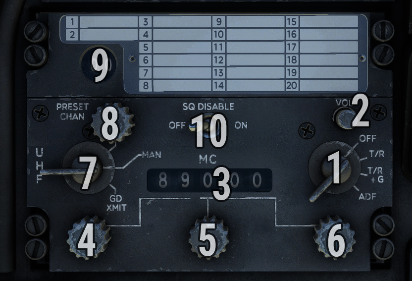
UHF/ADF panel is used to set ADF frequency.
-
On left side, a knob allows to switch between preset channels and manual frequency selection. You need to put this knob on MAN position in order to use your frequency (preset channels are not simulated).
-
On right side, the power knob needs to be set on ADF position.
| # | Description | # | Description |
|---|---|---|---|
| 1 | Power knob | 6 | Frequency knob (decimals) |
| 2 | Volume knob | 7 | Mode knob |
| 3 | ADF frequency | 8 | Preset channel knob |
| 4 | Frequency knob (tens) | 9 | Preset channel selection |
| 5 | Frequency knob (units) | 10 | Squelch disable switch |
In order to follow a NDB radial, please check BDHI section.
TACAN
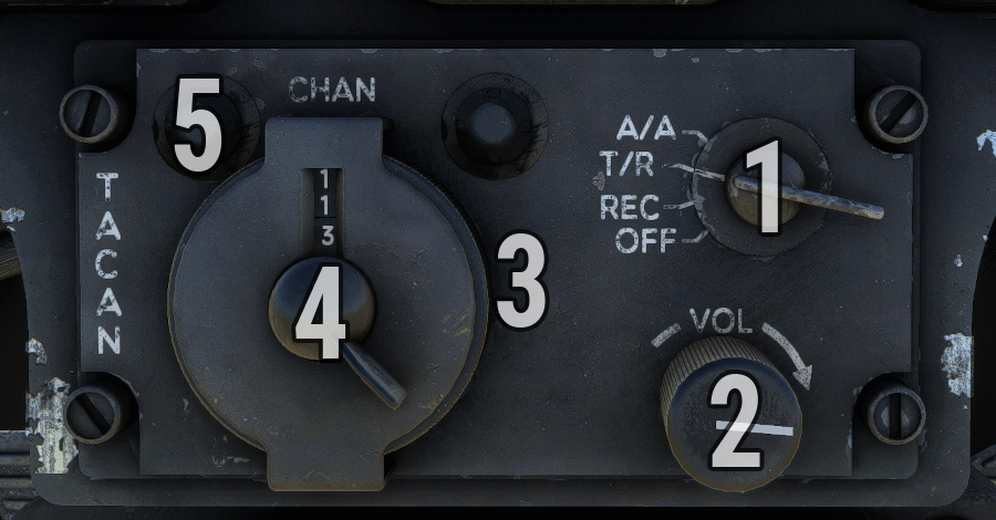
TACAN panel is located on center pedestal. Channel can be selected with two wheels on the left side.
A click spot has been added on top left in order to switch TACAN mode (X/Y), as older TACAN installations did not have mode selection.
Function knob is used to switch between different modes:
-
OFF: System off.
-
REC (Receive): System indicates magnetic bearing to selected station.
-
T/R (Transmit/Receive): System indicates magnetic bearing and distance to selected station.
-
A/A (Air/Air): System indicated distance to other TACAN-equipped aircraft (not simulated).
| # | Description | # | Description |
|---|---|---|---|
| 1 | Function knob | 4 | Channel setting wheel (third digit) |
| 2 | Volume knob | 5 | Mode setting button |
| 3 | Channel setting wheel (first two digits) |
In order to follow a TACAN radial, please check CDI section.
BDHI
Bearing-distance-heading indicator (BDHI) shows aircraft heading depending on compass panel settings.
It has the following control panel:
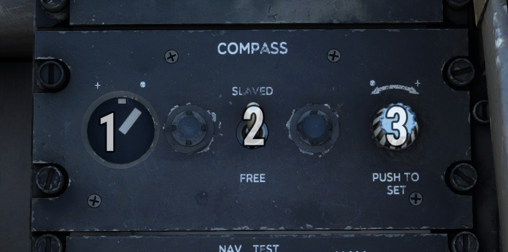
| # | Description | # | Description |
|---|---|---|---|
| 1 | Deviation annunciator | 3 | Gyro drift setting knob |
| 2 | Compass mode switch |
In SLAVED mode, compass operation is automatic with magnetic heading slaved to earth’s magnetic field as sensed by a remote compass transmitter.
In FREE mode, compass operation is tied to directional gyro and BDHI heading indication must be periodically corrected for gyro drift using PUSH TO SET knob (left or right rotation).
On the left, an annunciator shows disagreement between compass gyro and magnetic compass transmitter, in SLAVED mode only.
On the BDHI, small (simple) needle indicates direction to ADF station based on current frequency set on ADF panel.
Double needle indicates VOR (NAV frequency) or TACAN direction depending on current position of VOR/TACAN switch. If NAV is tuned to an ILS frequency, the needle will park to 90 degrees to avoid obstructing heading pointer.
On range indicator window, distance to TACAN station or to DME station (if NAV is equipped with DME) is indicated in nautical miles.
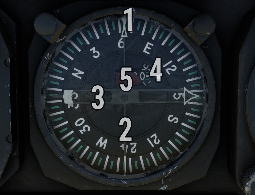
| # | Description | # | Description |
|---|---|---|---|
| 1 | Top heading pointer | 4 | Range indicator |
| 2 | ADF pointer | 5 | Warning flag |
| 3 | VOR/TACAN pointer |
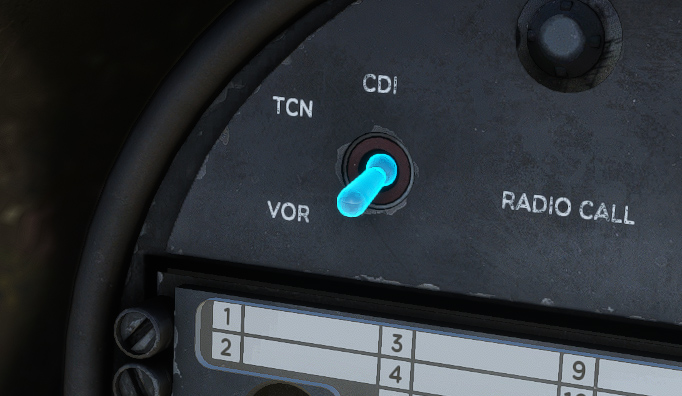
VOR/TACAN twitch is located on top left of instrument panel.
CDI
A course deviation indicator (CDI) is installed on instrument panel. Course is selected using the knob and indicated in top window.
Heading pointer indicates difference between current aircraft magnetic heading and selected course.
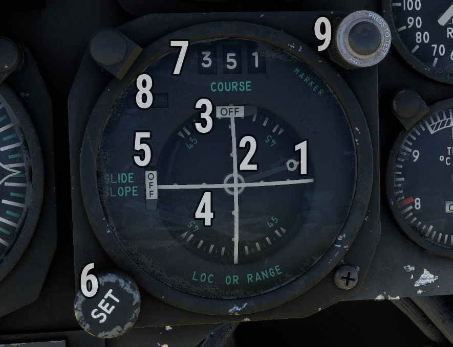
| # | Description | # | Description |
|---|---|---|---|
| 1 | Heading pointer | 6 | Course selection knob |
| 2 | Course deviation bar | 7 | Selected course |
| 3 | NAV flag | 8 | TO/FROM indicator |
| 4 | Glideslope deviation bar | 9 | ILS marker light |
| 5 | Glideslope flag |
Depending on current position of VOR/TACAN switch:
-
Course deviation bar shows current deviation from selected course based on VOR/ILS or TACAN station.
-
Glideslope bar shows current slope deviation in case of ILS approach.
Push-to-test light on top right corner will illuminate during ILS approaches when a marker is intercepted.
IFF/transponder
Identification friend or foe (IFF) panel is located on right console.
As IFF does not have any usage within the simulator, this panel is simplified and only used to manage aircraft transponder:
-
Power knob to switch between OFF, STDBY and NORM (ALT) states.
-
Four code dials (mode 3 section) to set transponder code.
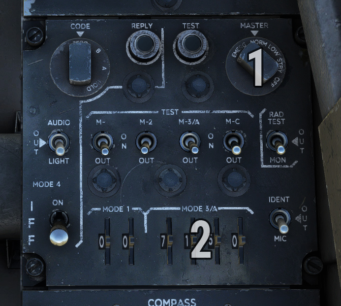
| # | Description | # | Description |
|---|---|---|---|
| 1 | Power/mode knob | 2 | Transponder code selection |
Optical sight
As the aircraft is capable of carrying varied munition loads, an optical sight is optionally fitted in the pilot’s field of view and can be displayed from the EFB.
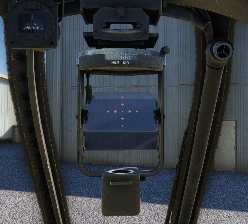
The sight is turned ON by turning the reticle brightness knob clockwise on gunsight control panel. The reticle consists of a 2 mil pipper with quarter markings.
Sight depression lever allows variable depression settings from 0 to 270 miles.
An adjustable polaroid filter can be lifted behind the reflecting glass during daylight operation in order to increase contrast between objects and the reticle.
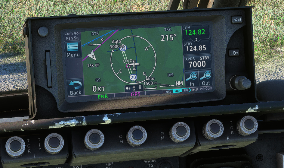
GPS
We fitted an optional GPS unit which you can display from the EFB. This unit is connected to COM1 and NAV1 frequencies. First option is to display Working Title GNS 430 which is available by default in the simulator. If you own PMS50 GTN or TDS Sim GTNXi add-ons, you can use their GTN 650 unit (PC only).