Electrical
Description
Main type of electrical power supply is 24 VDC, supplied by two batteries, two generators and ground power (if needed).
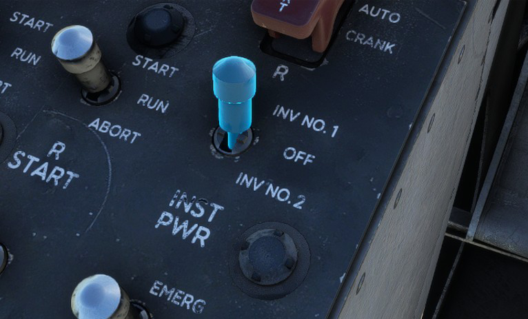
Some equipment requires AC (alternative current) which is made available by converting 24 VDC into 115 VAC using two inverters (one primary and one backup).
Electrical installation is divided into several busses to manage power distribution:
-
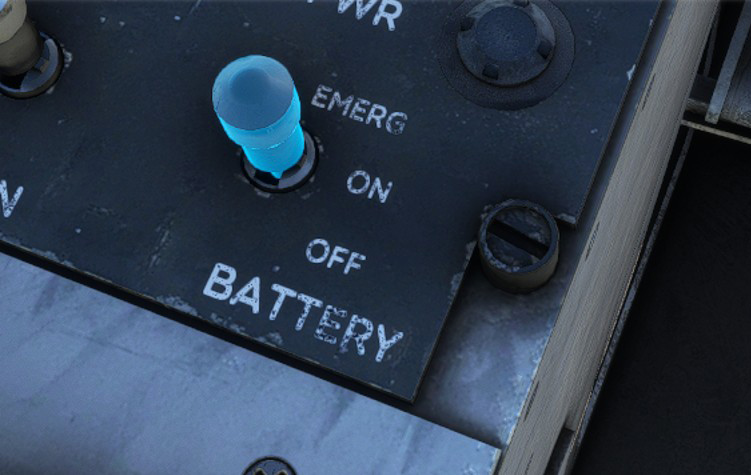
Battery bus (DC): provides power to emergency equipment and is powered by the batteries at all time.
-
Primary DC bus: main distributor of aircraft electrical power, providing power to all normal mission DC powered equipment.
-
Secondary DC bus: provides power for non-essential equipment (lighting, communications equipment).
-
Primary AC bus: provides power to instruments that need AC power.
Instruments are powered with the following switch (which toggles inverters):
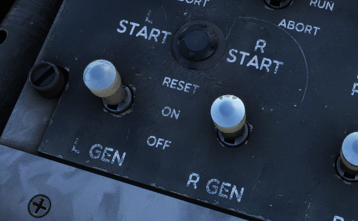
Batteries
Two 24 volts, 22 ampere hour nickel-cadmium batteries are installed for engine starting and emergency electrical power.
When fully charged, they are capable of providing sufficient power for approximately three unsuccessful engine ground start attempts.
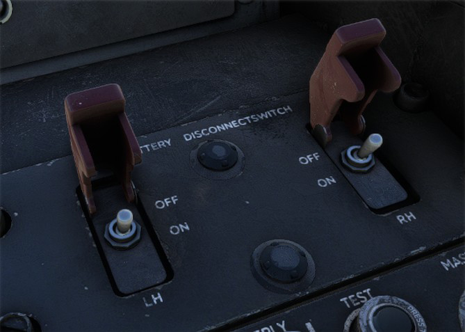
In addition to master battery switch on left console, each of the two batteries can be connected or disconnected from right console switches.
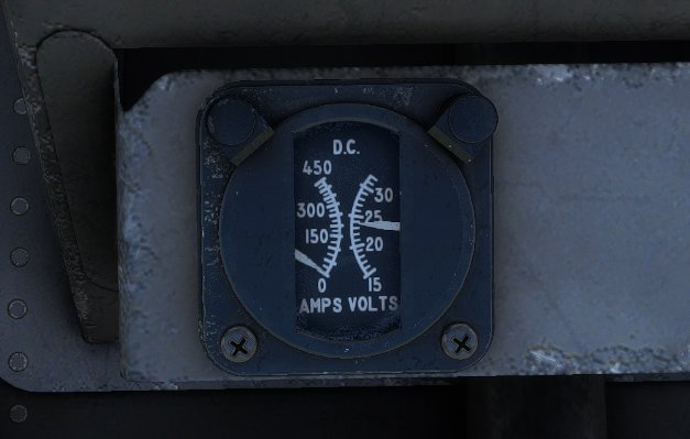
A gauge shows voltage of the primary bus, allowing to monitor the batteries state.
Generators
Each engine ships an independent generator, fully functioning once engines reach 50% RPM. They are supplying 30 volts DC at 300 amperes to the DC buses.
Single generator operation is capable of supplying sufficient power required for all electrical loads. They also act as engine starter motors during startup.
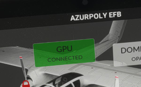
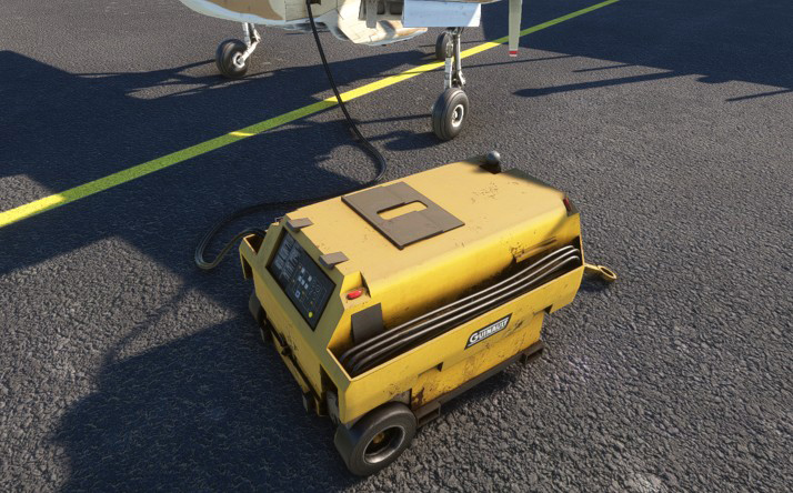
Ground power
External DC power can be used for engine starts when battery power is not sufficient.
It is plugged after clicking on the EFB button:
Lights
Exterior
Following exterior lights exist on the Bronco:
-
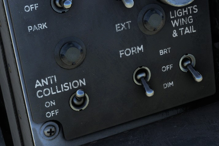
Anticollision (beacon) light.
-
Position (navigation) lights.
-
Formation lights.
-
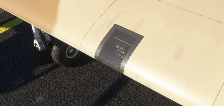
Taxi/landing lights.
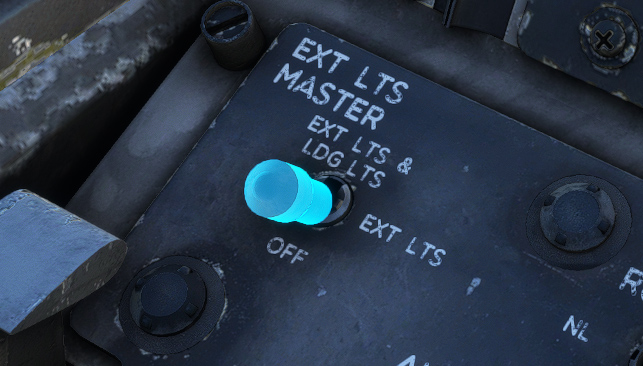
Master exterior lights switch, located on left console, allows to switch between three states:
-
OFF: all exterior lights are off irrespectively of other light switches.
-
EXT LTS: each exterior lights can be turned on with its dedicated switch.
-
EXT LTS & LDG LTS: same as previous position but taxi/landing lights are turned on.
Below front panel, anticollision light, position lights, and formation lights can be managed independently. Two different intensities can be selected (except for anticollision):
-
DIM: medium intensity.
-
BRT: higher intensity.
Original Bronco has a low intensity light in the nose for taxi/landing. Modern lights have been retrofitted on some modern models in the wings to have a better visibility during night flying. You can apply this modification from the EFB.
Interior
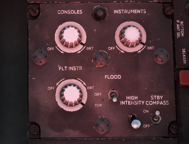
Interior lights are managed from right console:
-
Consoles lights (red light for side consoles).
-
Instrument lights (white light for secondary gauges).
-
Flight instrument lights (white light for most important gauges).
-
Flood lights (main panel).
-
High intensity lights (additional light for consoles).
-
Standby compass light.
-
Cargo bay light.
Alarms
Several alarms exist in the cockpit and are described in next subsections.
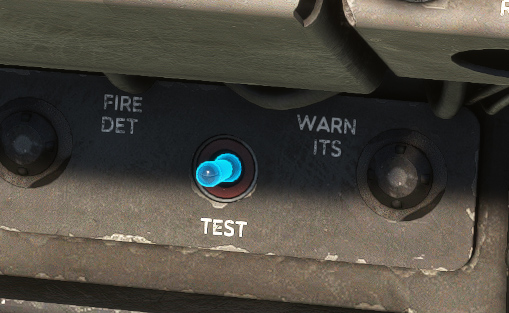
A three positions unstable switch allows to test alarms:
-
When held to the left, all alarms illuminate.
-
When held to the right, fire detection system is tested.
Alarms panel
This panel gathers main warning and caution lights (two colors depending on severity).
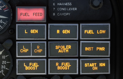
| LIGHT | COLOR | MEANING |
|---|---|---|
| Fuel feed warning | Red | Less than 50 pounds of fuel in feed tank |
| Generator caution One per engine | Amber | Generator off line |
| Fuel low caution | Amber | Less than 225 pounds of fuel in center wing tank |
| Chip warning One per engine | Red | Iron-metallic particles on chip detector |
| Spoiler authority | Amber | System malfunctioning if light stays on |
| Instruments power | Amber | Primary A-C bus (instruments) power failure |
| Fuel boost One per engine | Amber | Fuel boost pump motive flow output low |
| Start ignition on | Amber | Either engine starter or ignition operating |
Other alarms
WHEELS warning light is located on main panel to signal that landing gear is not down. This red light flashes when any gear is not securely extended and locked with at least one condition lever in T.O./LAND position and:
-
Both power levers retarded.
-
Or flaps are extended to 30 degrees or more.
A sound can also be heard with the same frequency.

Other warning lights are located below main panel hood. Those lights can be pushed to be tested and rotated in order to set their brightness.
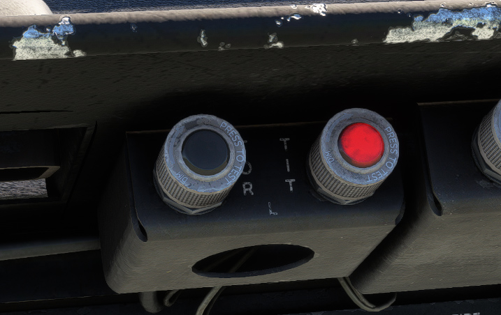
| Alarm | Color | Meaning |
|---|---|---|
| Overtorque caution (TOR) One per engine | Amber | Engine torque above 2,200 pound-feet |
| Overtemp caution (TIT) One per engine | Red | Engine turbine inlet temperature (TIT) above 996 °C |
| Battery warning One per battery | Red | Battery overheating |
| Hydraulic pressure | Amber | Hydraulic pressure below 200 PSI |
Stall
A rudder pedals shaking mechanism is incorporated in the aircraft. In the event of a stall, rudder pedals will start shaking to indicate to the pilot that aircraft is stalling.