Flight controls
Elevator, ailerons, and rudder are reversible, balanced mechanical systems operated by cables, rods, and bell cranks. The primary in-flight movement of the ailerons and elevator is accomplished through the aerodynamic action of spring and gear-operated boost tabs. Electrically operated trim bungees are responsible for control force trim, moving the flight control systems to no-load positions as needed.
Longitudinal system
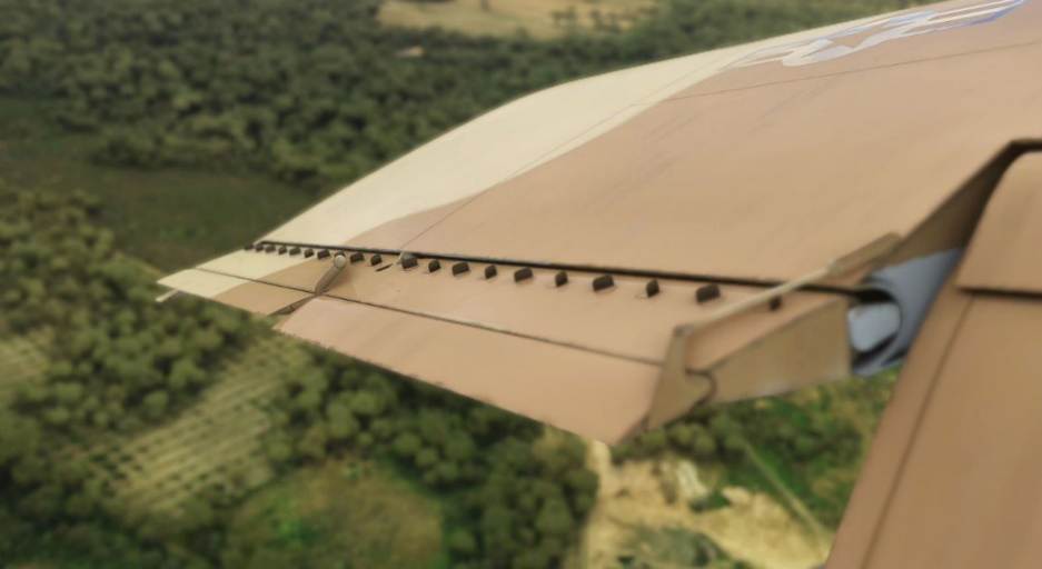
Longitudinal system (pitch) consists of a horizontal stabilizer and a tab-boosted elevator. The tab system consists of four trailing edge segments extending the entire span of the elevator.
In flight, the spring (outboard) tabs are driven by the control stick in the direction opposing desired elevator movement, displacing the elevator by aerodynamic reaction until spring tab stops are contacted.
Lateral system
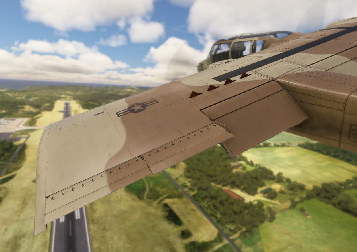
Lateral system consists of ailerons boosted by spring and gear tabs, augmented by spoilers. Operation of the outboard tabs is as follows: during in-flight control stick initial movement, the tabs are displaced, driving the ailerons by aerodynamic reaction until the spring tab stops are engaged. Subsequent lateral movement of the control stick directly actuates the ailerons.
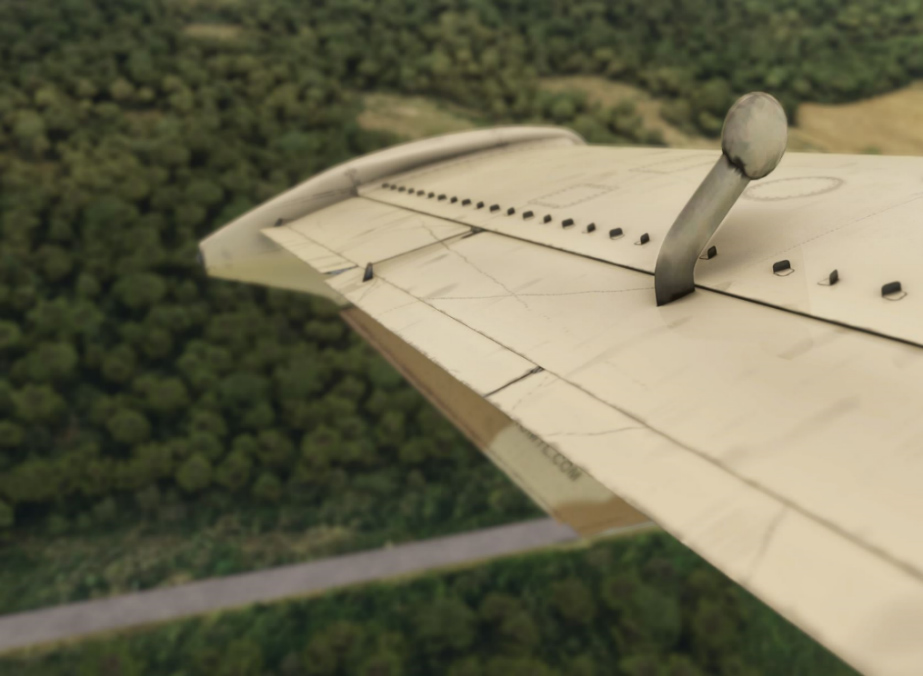
Four fan-shaped, axially hinged spoiler plates, rotating upward, are installed in each wing.
Displacement of the ailerons triggers mechanical linkage to rotate the spoiler plates upward from the down-going wing, generating extra rolling reaction as a result of lift loss. When the control stick reaches its maximum lateral travel, the spoilers are displaced by approximately 86 degrees.
Directional system
Directional system consists of dual vertical stabilizers, twin rudders, and an electromechanical yaw damper system. Rudders are not tab booster and are displayed by direct mechanical action through the rudder pedals.
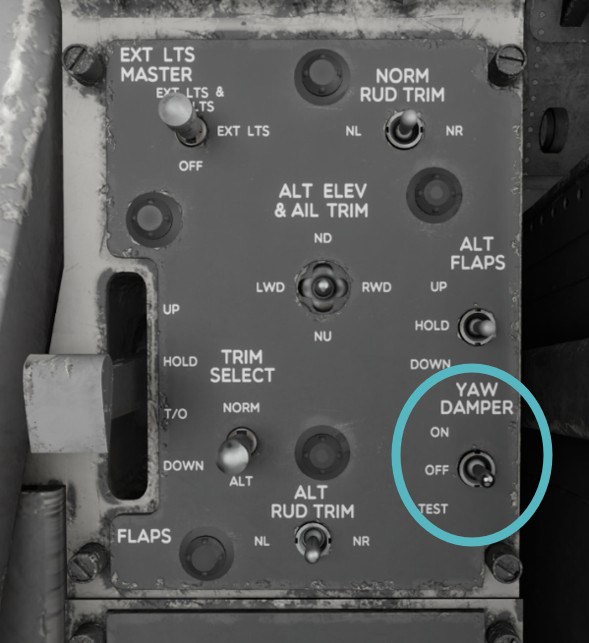
Yaw damper system supplies a control torque to the rudders proportional to aircraft yaw rate and oscillation frequency and in the opposite direction of the yaw motion. Pilot control of the system is obtained through a three-position toggle switch:
-
ON: normal position in flight.
-
OFF: yaw damper clutch is disengaged.
-
TEST: permitting damper system operational testing on ground.
When the aircraft is on ground (struts compressed), yaw damper is automatically disengaged.
Trim
Trim is available on the three axis and is fully electrical. Two separate circuits (normal and alternate) allow to handle any failure.
Elevator and aileron trim
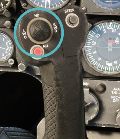
Regular aileron and elevator (roll and pitch) trim switch is located on the stick grip. This knob is not animated in the simulator as it is hardly usable.
Rudder trim
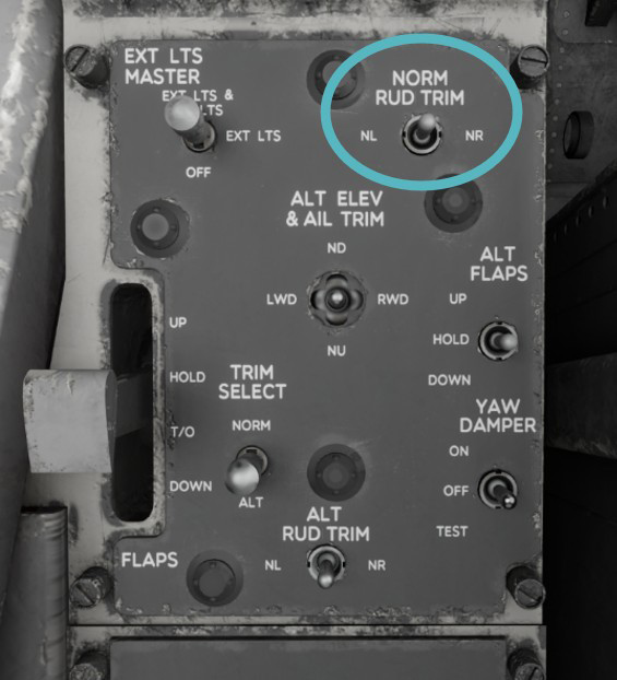
Rudder trim is actuated via NORM RUD TRIM switch located on left control panel.
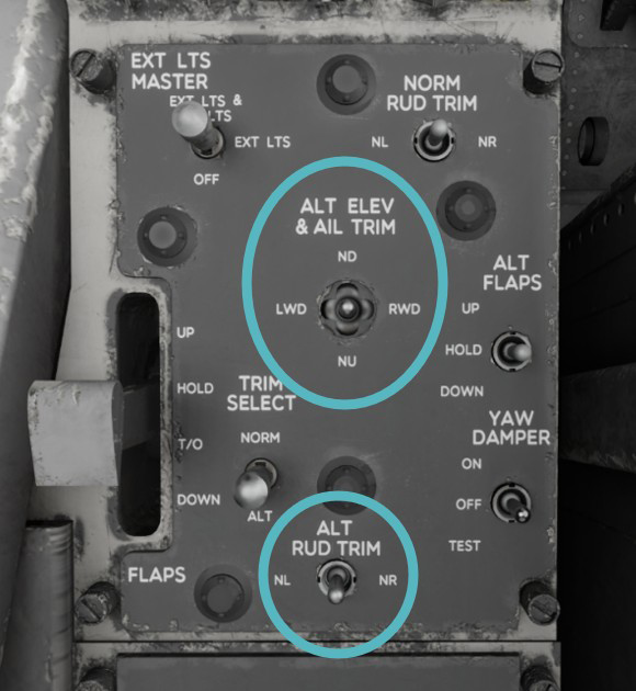
Alternate trim
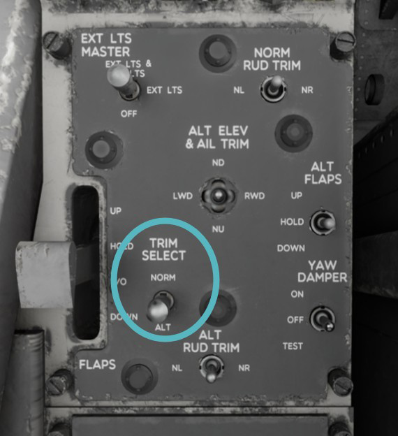
TRIM SELECT switch is positioned next to the flap handle. In the NORM position, primary DC bus power is allocated for aileron and elevator trim, regulated by the stick grip trim switch, and for rudder trim through the NORM RUD TRIM switch (panel-mounted), as described previously.
Switching to ALT position engages an alternate primary DC bus power source, and trim adjustments are made using the alternate elevator and aileron trim, as well as the alternate rudder trim switches.
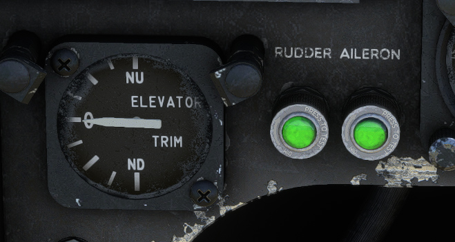
Trim indication
Main panel hosts the elevator trim indicator. This indicator shows trim position from full nose-up (NU) to full nose-down (ND).
Aileron and rudder trim neutral lights are installed on main instrument panel. Those green, press-to-test lights, powered by the primary DC bus, indicate neutral position for roll and yaw trim.