Engines
Turboprop model implemented in MSFS is based on a free-turbine engine (Pratt & Whitney PT6), where there are two separate shafts:
-
Gas generator shaft is connected to the compressor and the turbine responsible for extracting energy from the hot gases produced by combustion.
-
Power turbine shaft is connected to the propeller and is not directly linked to the gas generator shaft. Instead, it is driven by the flow of exhaust gases from the gas generator turbine.
Turboprop engines used in the OV-10 Bronco are Garrett T-76 types, which are fixed shaft engines. In a fixed-shaft engine, the turbine and the propeller are directly connected to a common shaft. This means that the rotation of the turbine directly drives the rotation of the propeller.
Fixed shaft engines are simpler in design but behave very differently as free-turbine engines, as any change in engine speed directly affect propeller speed.
As this type of engine is not simulated correctly in MSFS, we had to create an additional layer of custom code above default implementation to get a behaviour closer to a fixed-shaft engine, as explained in the following sections.
Description
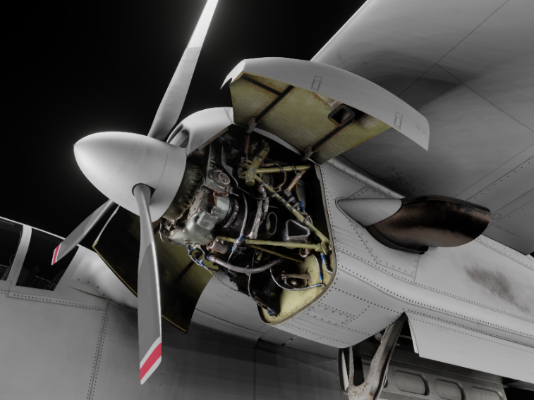
Aircraft is powered by two Garrett T-76 fixed-shaft turboprop engines, rated at 715 shaft horsepower. Left engine shaft rotates clockwise and right engine shaft counterclockwise, in order to reduce torque effects. Engine consists of a two-stage centrifugal compressor, a three-stage axial turbine and a reduction gearbox.
Each engine drives a 8.5 feet, three-blade, fully reversible aluminum propeller. At maximum engine RPM (41,730), propeller rotates at 2000 RPM. Propeller pitch is adjusted by varying the oil pressure in the propeller dome, meaning it will automatically feather when engine is shut down, as oil pressure will be lost.
As it is a fixed-shaft turboprop, propeller is directly linked to the gas producer of the engine. It means that a feathered propeller needs a lot of torque to overcome the drag induced when it starts spinning. Starting with a feathered propeller is impossible as starter will have to turn both the gas producer and the feathered propeller, which will lead to engine overheating.
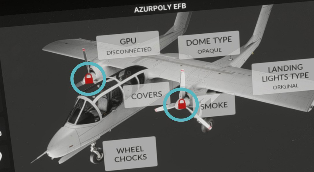
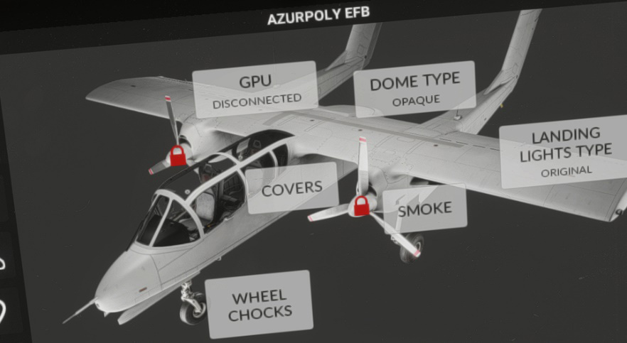
To prevent this, a specific mechanism called “start latches” is built into the propeller dome. Those latches can lock the propeller blades in flat pitch (close to zero degrees) where they produce very little drag. They are typically used when engine is shut down, to avoid the propellers from feathering, simplifying the next startup.
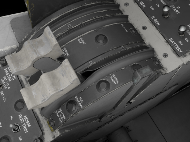
Condition levers
Condition levers control the fuel flow to the engines and have four distinct positions. They are linked to the power management control system, the engine fuel shutoff valve, and the propeller feather valves. Primary function of the condition levers is to initiate or stop fuel flow to the engines, and to select between two different power settings.
The four positions are:
-
FEATHER & FUEL SHUT-OFF: feathers the propellers and stop engines fuel feed.
-
FUEL SHUT-OFF: fuel is shut off but propeller feather valves are kept close, hence propellers are not necessarily feathered (depending on power levers position).
-
NORMAL FLIGHT: normal position with minimal engine RPM (60% on ground).
-
T.O./LAND: position for take-off and landing, where higher engine RPM is maintened (minimum 95%), in order to have quick response to any change in power lever commands.
Controller bindings
Condition levers can be bound to physical controller axis/buttons to avoid using the mouse for each movement.
The following bindings are supported (see controls options in MSFS settings):
| BINDING NAME | EVENT | DESCRIPTION |
|---|---|---|
| CONDITION LEVER 1 AXIS | AXIS_CONDITION_LEVER_1_SET | Set lever position (axis) for engine #1 |
| CONDITION LEVER 2 AXIS | AXIS_CONDITION_LEVER_2_SET | Set lever position (axis) for engine #2 |
| CONDITION LEVER AXIS | AXIS_CONDITION_LEVER_SET | Set lever position (axis) for both engines |
| SET CONDITION LEVER 1 | CONDITION_LEVER_1_SET | Set lever position for engine #1 |
| SET CONDITION LEVER 2 | CONDITION_LEVER_2_SET | Set lever position for engine #2 |
| SET CONDITION LEVER | CONDITION_LEVER_SET | Set lever position for both engines |
| INCREASE CONDITION LEVER 1 | CONDITION_LEVER_1_INC | Increase lever position for engine #1 |
| INCREASE CONDITION LEVER 2 | CONDITION_LEVER_2_INC | Increase lever position for engine #2 |
| INCREASE CONDITION LEVER | CONDITION_LEVER_INC | Increase lever position for both engines |
| DECREASE CONDITION LEVER 1 | CONDITION_LEVER_1_DEC | Decrease lever position for engine #1 |
| DECREASE CONDITION LEVER 2 | CONDITION_LEVER_2_DEC | Decrease lever position for engine #2 |
| DECREASE CONDITION LEVER | CONDITION_LEVER_DEC | Decrease lever position for both engines |
You can see more details for axis settings in EFB section.
Power levers
Power levers are linked to the engine fuel control units and the power management control system, and can be moved in four different zones. Primary function of the power levers is to control engine fuel flow (depending on condition lever position) and propeller thrust, and to select reverse thrust.
The four sections are:
-
FULL REVERSE: drives the propeller blades against the reverse pitch stops to obtain maximum reverse thrust, and automatically provides required fuel flow for reverse thrust conditions.
-
GROUND START: minimum torque at idle RPM with propeller blades set at flat pitch position.
-
FLIGHT IDLE: provides minimum fuel flow and torque, depending on airspeed.
-
MILITARY: provides maximum fuel flow and torque.
Selection of reverse thrust and ground start position is prevented in flight by a switch linked to the landing gear.
Controller bindings
Power levers are using throttle axis by default. Positive throttle zone goes from FLIGHT IDLE to MILITARY positions, and reverse throttle zone goes from GROUND START to FULL REVERSE.
You can decide to manage the full range of power lever with your throttle (from FULL REVERSE to MILITARY positions), or to use buttons to toggle reverse, see EFB section. You can also change axis settings from the EFB.
The following bindings are supported (see controls options in MFS settings):
| BINDING NAME | EVENT | DESCRIPTION |
|---|---|---|
| THROTTLE 1 AXIS | AXIS_THROTTLE1_SET | Set lever position (axis) for engine #1 |
| THROTTLE 2 AXIS | AXIS_THROTTLE2_SET | Set lever position (axis) for engine #2 |
| THROTTLE AXIS | AXIS_THROTTLE_SET | Set lever position (axis) for both engines |
| FULL THROTTLE 1 | THROTTLE1_FULL | Set engine #1 power to 100% |
| FULL THROTTLE 2 | THROTTLE2_FULL | Set engine #2 power to 100% |
| FULL THROTTLE | THROTTLE_FULL | Set both engines power to 100% |
| THROTTLE 1 CUT | THROTTLE1_CUT | Set engine #1 power to 0% |
| THROTTLE 2 CUT | THROTTLE2_CUT | Set engine #2 power to 0% |
| THROTTLE CUT | THROTTLE_CUT | Set both engines power to 0% |
| THROTTLE 1 INCREASE | THROTTLE1_INCR | Increase lever position for engine #1 |
| THROTTLE 2 INCREASE | THROTTLE2_INCR | Increase lever position for engine #2 |
| INCREASE THROTTLE | THROTTLE_INCR | Increase lever position for both engines |
| N/A | INCREASE_THROTTLE | Increase lever position for both engines |
| THROTTLE 1 INCREASE (SMALL) | THROTTLE1_INCR_SMALL | Increase lever position for engine #1 |
| THROTTLE 2 INCREASE (SMALL) | THROTTLE2_INCR_SMALL | Increase lever position for engine #2 |
| INCREASE THROTTLE (SMALL) | THROTTLE_INCR_SMALL | Increase lever position for both engines |
| THROTTLE 1 DECREASE | THROTTLE1_DECR | Decrease lever position for engine #1 |
| THROTTLE 2 DECREASE | THROTTLE2_DECR | Decrease lever position for engine #2 |
| DECREASE THROTTLE | THROTTLE_DECR | Decrease lever position for both engines |
| N/A | DECREASE_THROTTLE | Decrease lever position for both engines |
| THROTTLE 1 DECREASE (SMALL) | THROTTLE1_DECR_SMALL | Decrease lever position for engine #1 |
| THROTTLE 2 DECREASE (SMALL) | THROTTLE2_DECR_SMALL | Decrease lever position for engine #2 |
| DECREASE THROTTLE (SMALL) | THROTTLE_DECR_SMALL | Decrease lever position for both engines |
| N/A | TOGGLE_THROTTLE1_REVERSE_THRUST | Toggle reverse for engine #1 |
| N/A | TOGGLE_THROTTLE2_REVERSE_THRUST | Toggle reverse for engine #2 |
| TOGGLE THROTTLE REVERSE THRUST | THROTTLE_REVERSE_THRUST_TOGGLE | Toggle reverse for both engines |
| N/A | SET_THROTTLE1_REVERSE_THRUST_OFF | Disable engine #1 reverse |
| N/A | SET_THROTTLE2_REVERSE_THRUST_OFF | Disable engine #2 reverse |
| N/A | SET_REVERSE_THRUST_OFF | Disable reverse for both engines |
| N/A | SET_THROTTLE1_REVERSE_THRUST_ON | Enable engine #1 reverse |
| N/A | SET_THROTTLE2_REVERSE_THRUST_ON | Enable engine #2 reverse |
| N/A | SET_REVERSE_THRUST_ON | Enable reverse for both engines |
For now, throttle axis cannot be bound using external software (FSUIPC, SPAD, etc) because of a simulator limitation. A workaround has been implemented and is explained in CONTROL ASSIGNMENTS SECTION.
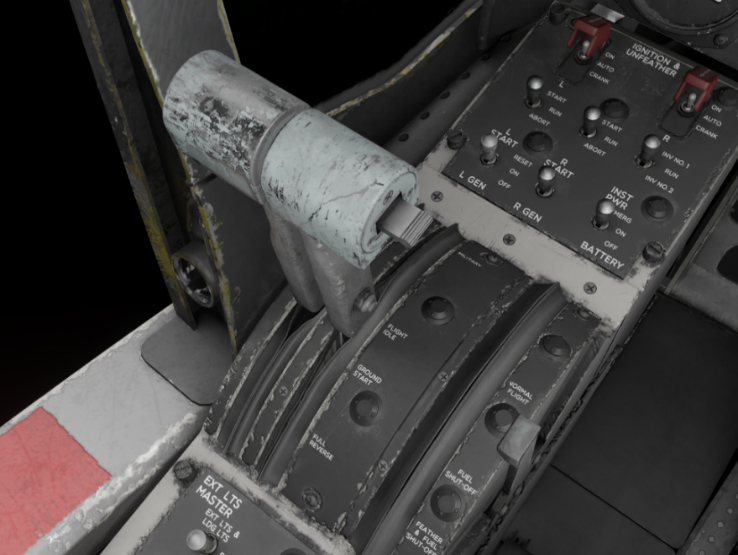
Start panel
This panel positioned on the left console allows to manage engine start sequence, both on ground and in flight, along with unfeathering function:
-
START switches are used on ground to engage engine start sequence. Those three-position switches are marked START, RUN, and ABORT, and return to RUN position on release. Holding the switch momentarily in START position initiates engine starter operation. ABORT position disengages the holding circuit, disables automatic ignition circuit and the starter.
-
IGNITION & UNFEATHER switches are used to operate propeller unfeathering pumps and for air start. AUTO is their default position. CRANK will turn unfeather pump on, supplying oil pressure to the propeller governor and setting propeller angle within the beta range. When used in flight, propeller will start windmilling due to the drag they produce. ON position also triggers unfeather pump, but fuel is introduced for an air-start along with ignition.
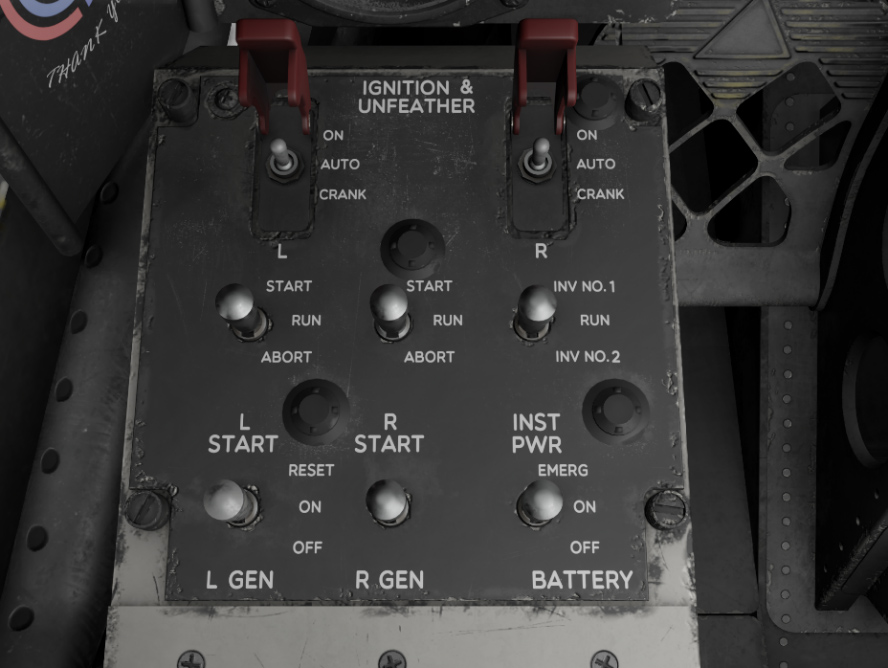
OV-10B variants also have “continuous ignition” switches on the front panel, which are used to reduce engine flameouts risks when flying in icing conditions.
Operation
On ground
As explained in previous sections, propellers must be “on the latches” (start latches engaged) and not feathered before starting the engine. In order to start, put the starter switch on START position and move condition lever to NORMAL FLIGHT position once 10% RPM is reached. Engine will stabilize at approximately 60% RPM.
In order to “unlock” start latches, power lever needs to be briefly put in reverse range. At this moment, propeller can operate in their full beta range. You can check on the EFB that padlock logo disappeared.
While taxiing, condition lever should be kept in NORMAL FLIGHT position and power levers can be used in their full range to get desired thrust. Reverse range is commonly used when taxiing the Bronco in order to turn more easily by using differential thrust.
Before takeoff, condition lever is put in T.O./LAND position which will set the engine at 95% RPM minimum, ensuring a quick response to power lever changes.
In flight & failures
After takeoff, condition lever can be set in NORMAL FLIGHT position for the whole flight. Before landing, condition lever is set again in T.O./LAND position to ensure a quick response to any power change.
In case of engine failure or shutdown while in flight, the propeller will be automatically feathered as a result of the huge aerodynamic load. The propeller control systems also incorporate dump (feather) valves which allow the pilot to manually select feathering as required (using condition levers).
In order to restart engine in flight, IGNITION & UNFEATHER switch needs to be placed on position ON, which will run unfeather pump and initiate an engine start thanks to windmilling.
Monitoring
Engine is monitored with several gauges positioned on main instrument panel:
-
Torque on each engine shaft.
-
Engine RPM (percent).
-
EGT (Exhaust Gas Temperature) / TIT (Turbine Inlet Temperature).
-
Oil pressure.
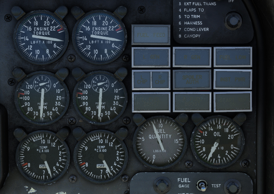
EGT/TIT gauge is important as the engine can be subject to overheating. During engine startup, EGT is indicated, which is the temperature of the exhaust gases. Once 50% RPM is reached, TIT is indicated. TIT corresponds to the temperature of combustion chamber gases as they enter the turbine unit. It is a “virtual” parameter as no probe could support the temperature at this location. It is calculated from EGT value, taking several other parameters into account. TIT is easier to monitor as its maximum allowable value is always approximately 1000 °C, whatever the altitude, airspeed and engine RPM.
TIT warning lights will light up at 996 °C.
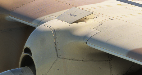
Oil temperature is automatically regulated, with a radiator located above each engine. Oil cooler flaps are directly linked to landing gear operation and are opened when landing gear is extended, allowing to increase oil cooling at low speeds.
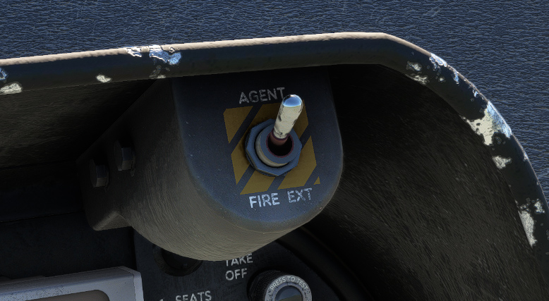
Fire
Two handles located on main panel will light in red in case of engine fire.
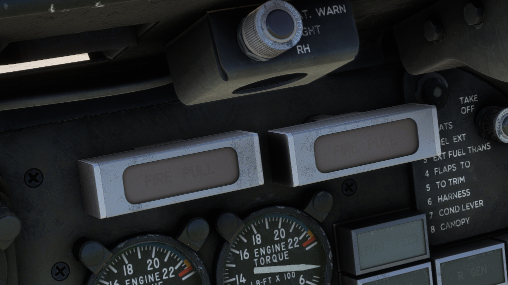
Pulling one of the handles will close emergency fuel valve of the engine in order to stop fuel feeding.
Each engine has a dedicated fire extinguisher system installed in its nacelle. This system is armed by the respective FIRE PULL handle, and completely discharged when FIRE EXT switch is placed to AGENT position.