Hydraulics
The Bronco has hydraulic power used for:
-
Landing gear operation.
-
Flaps.
-
Nose wheel steering.
-
Wheel brakes.
Flight controls are fully mechanical and do not need any hydraulic power.
Hydraulic generation
Hydraulic generation consists of a single circuit with an electrically operated hydraulic pump. Hydraulic power at 1,500 to 1,550 psi is supplied by this system. Hydraulic power package, including the reservoir and hydraulic pump, is installed as a swing-down assembly above the cargo bay, aft of the wing. This hydraulic power is necessary for the normal extension and retraction of the landing gear, the normal extension and retraction of wing flaps, as well as for the nose wheel steering system.
During nonduty periods, hydraulic pump is turned off, leaving residual pressure in the lines last pressurized.
Brake hydraulic lines are fed by a separate manually operated hydraulic system and actuated by both rudder pedals.
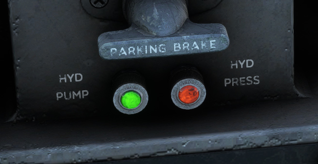
Two lights allow to monitor hydraulic generation:
-
Green light on when hydraulic pump is operating.
-
Amber light on when hydraulic pressure is falling below 200 psi.
Landing gear
Landing gear
The Bronco has a tricycle-type landing gear, with main gear retracting backwards and nose gear retracting forward. It is hydraulically actuated. In case of power failure or a malfunction in the normal extension circuit, the gear can be extended manually but not retracted.
When on ground, a safety switch will prevent any retractation of the landing gear. Normal retraction requires approximately 10 seconds, and extension requires approximately 7 seconds.
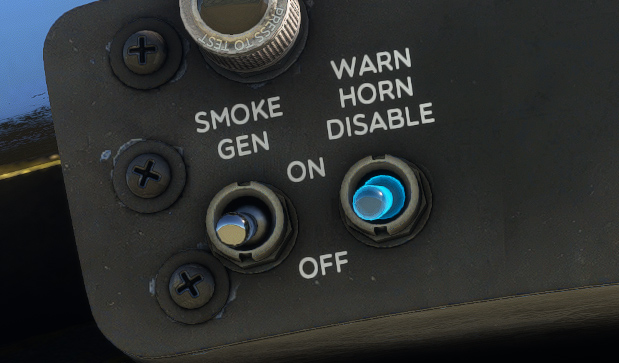
Landing gear warn horn
As described in alarms section, a landing gear warning horn will sound simultaneously with the WHEELS warning light illumination. This horn can be turned off by momentarily positioning the WARN HORN DISABLE switch to OFF.
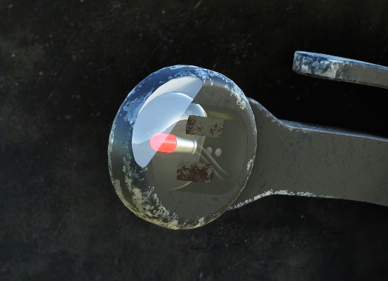
Landing gear unsafe light
The pilot's landing gear handle incorporates a gear unsafe light. This red light is illuminated whenever the landing gear is not locked in the position demanded by the gear handle.
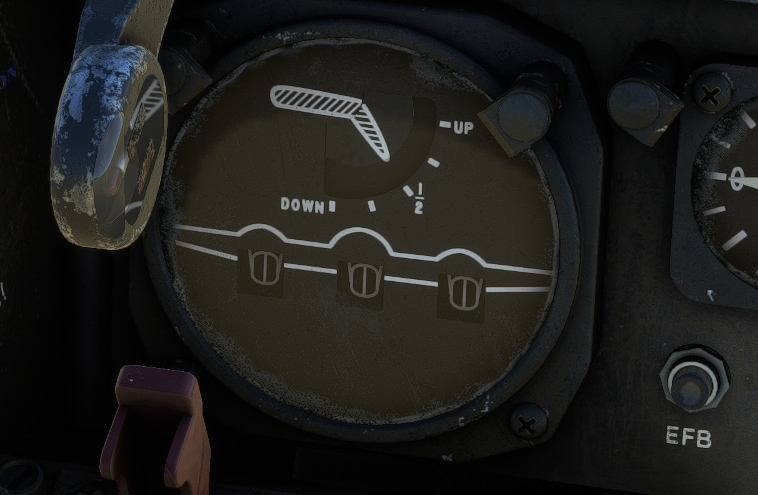
Landing gear position indicator
Landing gear position indicator is located on main panel, integrated with flaps position indicator. Landing gear position is reflected by an indicator for each gear. Landing gear up, down, and intermediate positions are indicated.
Steering
Nose wheel steering can move 55 degrees left or right, facilitated by a hydraulically operated nose wheel steer-damper system. When the aircraft is resting on the landing gear, hydraulic system pressure is directed through a steering control valve to the steer-damper unit.
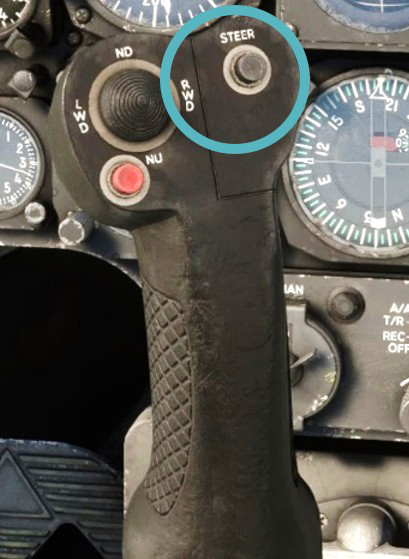
The STEER button for the nose wheel is located on the front side of the pilot's stick grip. In the real Bronco, continuous depression of this button is needed in order to operate nose wheel steering.
In the simulator, the system is simplified and nose wheel steering is enabled by default. You can disable steering by pushing the STEER button, and you will need to taxi using differential engine thrust, as it is commonly done on the real aircraft.
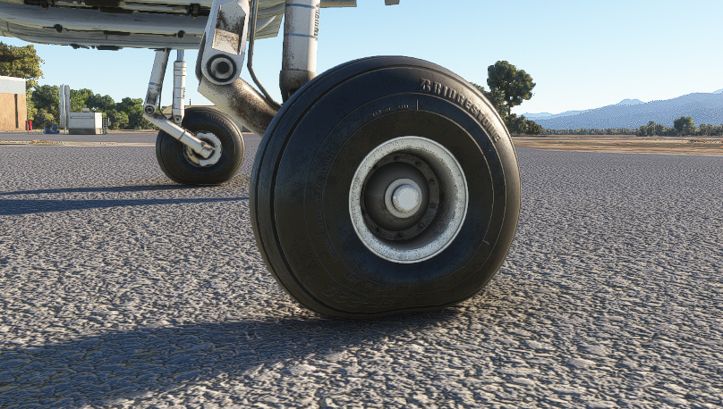
Tires
Tires are key components as the Bronco is commonly used to land on rough terrains. Tire pressure and effect of aircraft weight has been simulated. You can change tire pressure from the EFB.
Flaps
A wing flap system with four sections, featuring slots, is integrated into the aircraft. Each wing has one inboard and one outboard section positioned on either side of the tail boom. Hydraulic system power ensures standard operation.
Flaps can be set to any position between 0 and 40 degrees.
Slot doors on the lower wing surface, extending mechanically with the flaps, manage boundary layer airflow.
Additionally, an electrically powered alternate flap system is available for extending and retracting control in case of hydraulic system failure or normal flap control circuit failure.
Flaps position indicator
Flaps position indicator is integrated with landing gear position indicator on main panel, indicating up, ¼, ½, ¾, and down positions.
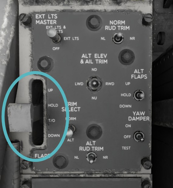
Flaps handle
Flaps handle is located on the left console, in order to operate flaps through their 40° range, with four separate positions:
-
UP to set flaps up.
-
HOLD to stop flaps at their current position.
-
T/O to set flaps to takeoff position (20 degrees).
-
DOWN to set flaps fully down.
Flaps are fully retracted in approximately eight seconds.
You cannot bind a controller axis to the exact same positions as this lever because of technical limitations (HOLD position does not exist in the simulator). However, you can bind up, takeoff and down positions and lever will move accordingly.
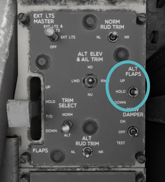
Alternate flaps switch
ALT FLAPS switch is located on the control panel (left console).
In case of failure in the normal hydraulic power or electrical control, alternate flaps switch can be used to reach the desired flaps position, with power supplied by primary DC bus.
When using ALT FLAPS switch, make sure that FLAP handle is in HOLD position to prevent unintentional activation of the normal flaps system. The switch has UP, HOLD, and DOWN positions and is spring-loaded to the HOLD position.
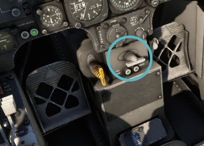
Brakes
Hydraulically independent wheel brakes, manually operated, are installed. Each wheel has its own brake master cylinder, activated by pressure on the rudder pedals.
PARK BRAKE handle is located on the pilot's center pedestal. To engage parking brake, pedal pressure is applied as needed, followed by pulling out the handle and releasing pedal pressure.