Avionics
The Jaguar A had pretty basic avionics compared to later versions, which were fitted with more modern equipment like inertial navigation system.
All avionics are described in this section.
COM/NAV
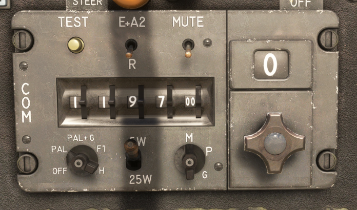
V/UHF panel (called COM in our aircraft) is used for communications in VHF and UHF. It is powered with the bottom left knob on “PAL” position.
This panel is displaying active COM1 frequency which can be modified with the dials.
Other switches and preselected frequency knob (on the right) are not used in the simulation.
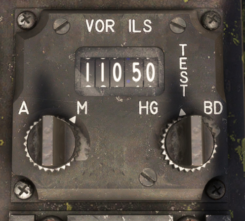
VOR/ILS panel is used to set NAV1 frequency, to navigate to a VOR or to fly an ILS approach.
On the left, a combined control with:
-
A central dial to set the frequency in MHz.
-
A ring with “A” (OFF) and “M” (ON) positions.
On the right, a combined control with:
-
A central dial to set the frequency in KHz.
-
A ring to test the equipment: “HG” will move sphere indicator deviation bars on top-left position, “BD” will move deviation bars on bottom-right position.
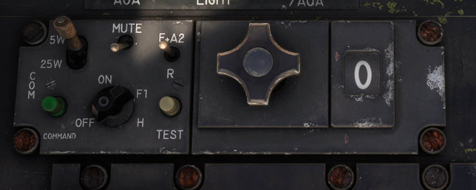
UHF2 panel, located on left console, is animated but does not have any usage in the simulator.
TACAN
TACAN panel is mounted on the left console, with a window displaying the active channel.
Left knob is used to set the channel tens (00 to 12, as channel goes from 0 to 126).
Right knob is a combined control with:
-
A central dial to set the channel units (0 to 9).
-
A ring to set current mode:
-
OFF: system off.
-
REC: reception mode.
-
T/R: transmission and reception (needed to get station distance).
-
A/A: air-to-air mode (not simulated).
-
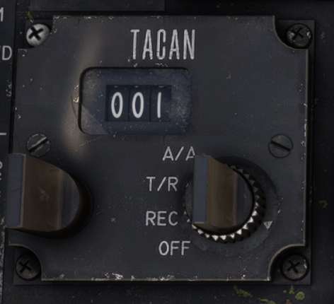
Switch between X/Y modes can be done by clicking on the channel window frame, or from the EFB tablet (second tab).
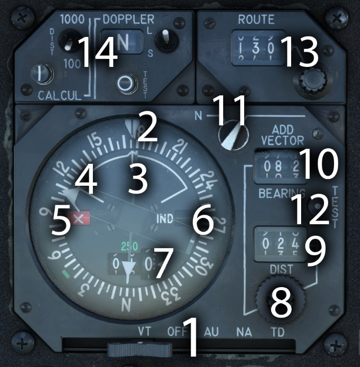
Navigation indicator
Navigation indicator is based on a central rose, indicating current aircraft heading.
| # | Description | # | Description |
|---|---|---|---|
| 1 | Operating mode selector | 8 | Additional vector setting knobs |
| 2 | Leeway (deviation) indicator | 9 | Additional vector distance |
| 3 | Single needle (VOR/GPS) | 10 | Additional vector bearing |
| 4 | Double needle (TACAN) | 11 | Normal / additional vector knob |
| 5 | VOR/LOC failure flag | 12 | Indicator test button |
| 6 | Indicator failure flag | 13 | Course (CRS) selection |
| 7 | TACAN distance indicator | 14 | Doppler panel |
Mode selector has five positions:
-
VT: VOR + TACAN.
-
OFF: power off.
-
AU: autonomous (emergency mode, same as VT in the simulator).
-
NA: navigation (not simulated, same as VT in the simulator).
-
TD: TACAN + Doppler (same as VT position, but showing deviation using Doppler calculation).
If NAV1 frequency is tuned to a VOR, single needle shows VOR station bearing. If GPS drives NAV1, the needle shows GPS target (or waypoint) direction.
If TACAN panel is powered (REC or T/R) and tuned to a detectable TACAN station, double needle will show its bearing. Station distance is displayed on the bottom (TACAN in T/R mode).
The same course setting (CRS) is used for VOR and TACAN.
Doppler panel commands Doppler radar settings. This radar is used to compute the components of the ground speed of the aircraft, and acceleration variations.
When test button is pressed with the instrument powered, double needle should do in the zone materialized by a green arc, distance should indicate 250 and the three flags should be displayed.
Additional vector
This function is used in conjunction with TACAN to set an offset and target a custom “virtual” point.
In order to enable “additional vector”, you must first ensure that the small knob on the top right of the indicator is on the correct position. Also, a valid TACAN station should be detected.
Then, you need to set the desired offset of the custom point to target (bearing and distance from the TACAN station).
The double needle will give you the bearing to this custom point.
Please note that using this function will not change the information displayed on the sphere indicator (deviation from TACAN course and TO/FROM flag).
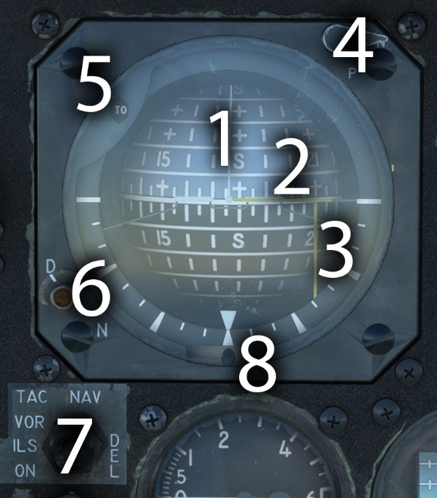
Sphere indicator
Sphere indicator serves multiple purposes. Black hemisphere represents the earth, and the gray hemisphere symbolizes the sky. The equator represents the horizon. This sphere is slaved in heading, with roll and pitch displayed behind a fixed aircraft symbol.
Heading is read on the meridians, engraved every 10° on the sphere. Roll is represented by the tilt of the sphere, and the reading is taken from the roll scale, which is graduated every 10°. Pitch is read on the parallels of the sphere, engraved every 10°, aligned with the fixed aircraft symbol.
| # | Description | # | Description |
|---|---|---|---|
| 1 | Attitude and heading indication | 5 | TO/FROM flag |
| 2 | Vertical deviation bar | 6 | ILS marker light and day/night setting |
| 3 | Horizontal deviation bar | 7 | VOR-ILS / TACAN selector |
| 4 | Normal / pole mode switch and test on press | 8 | Slip ball |
This instrument is also used for radionavigation, depending on the position of the switch located on the bottom left:
-
Vertical deviation bar (yellow) shows deviation with VOR course or TACAN course. In VOR-ILS mode, deviation with GPS course is displayed if GPS drives NAV1.
-
Horizontal deviation bar (yellow) only works in VOR-ILS mode. It shows vertical ILS deviation (glideslope) or vertical deviation from the GPS if GPS drives NAV1.
-
TO/FROM flag shows if the aircraft is going to, or coming from the target station.
A marker indicator light, with a lighting switch for night and day, will illuminate during an ILS approach when a marker is detected. This light can be tested by pressing normal / pole mode switch.
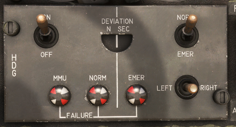
Heading control panel
The gyroscopic unit, the magnetic monitoring unit (MMU) and the emergency directional gyro are mounted in the nose of the aircraft. The magnetic detector is located in the vertical stabilizer.
This panel is gathering those different information to transmit the gyroscopic information and aircraft heading to the different instruments like navigation indicator and sphere indicator.
Three different magnetic indicators are signaling a failure of:
-
Magnetic monitoring unit (MMU).
-
Heading or vertical gyro failure in the gyroscopic unit.
-
Secondary gyroscopic unit failure (used for secondary attitude indicator).
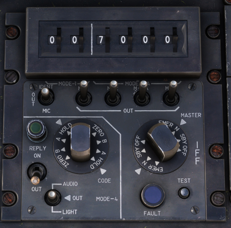
IFF/Transponder
As IFF (identification, friend or foe) does not have any usage within the simulator, this panel is simplified and only used to manage aircraft transponder, with:
-
Power knob to switch between OFF, STDBY, NORM (ALT) and EMER states.
-
Four code dials (top right section) to set transponder code.
The rest of the panel is animated but inoperative.
HUD
The heads-up display consists of a sighting head and an adapter box.
It features:
-
A clear semi-reflective glass.
-
A four-lens objective, with a 120 mm output diameter.
-
A three-position function selector (approach, air-air, air-ground).
-
A target elevation with adjustment drum.
-
A mode selector mode (approach, air-air, air-ground).
-
Two brightness setting knobs.
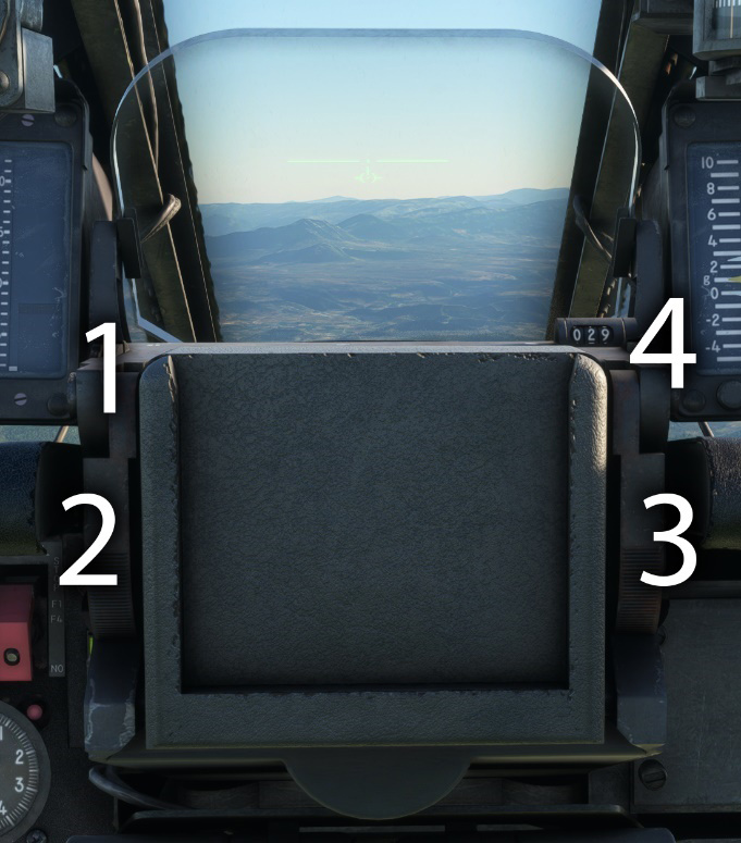
| # | Description | # | Description |
|---|---|---|---|
| 1 | HUD mode selector | 3 | Fixed reticle brightness knob |
| 2 | Mobile reticle brightness knob | 4 | Target elevation setting |
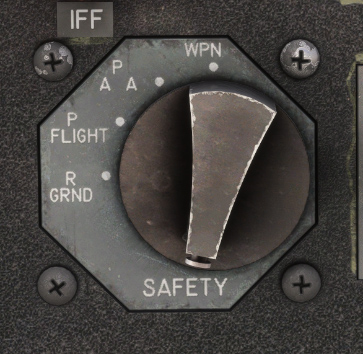
The heads-up display is powered depending on the position of armament safety knob (flight preparation, air-air preparation or armed).
In all of the three modes, the fixed reticle is the plane reference.
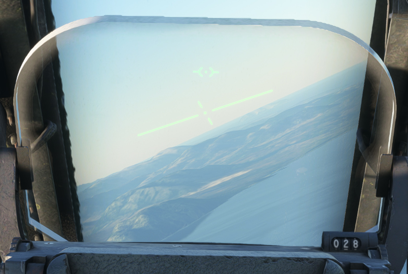
Approach mode
In this configuration, mobile reticle represents aircraft flight path, and is rotating to stay on the horizon line.
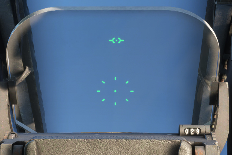
Air-air mode
This mode is used for air-to-air combat.
Mobile reticle is a circle made of dots with the aiming point at its center. As the G-force increases, the distance between the fixed reticle and the mobile reticle also increases.
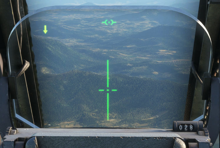
Air-ground mode
This mode is used for air-to-ground combat.
Mobile reticle indicates striking point, based on elevation setting on the right.
On the left part, a symbol is displayed depending on radio height index (set on the instrument):
-
Arrow down if aircraft is above the target height.
-
Arrow up if aircraft is below the target height.
-
Circle if aircraft is at the target height (+/- 50 feet).
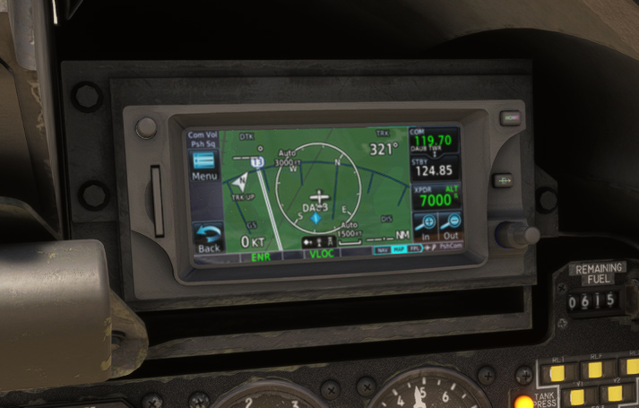
GPS
Even though GPS was not really used in aviation when the Jaguar A was operated, we decided to add an option to use GPS units (GNS 430 or GTN 650).
The unit can be displayed on two different locations (instruments panel or right console), set from the EFB tablet.
Autopilot
The aircraft is fitted with a very basic autopilot, managed with three buttons located on the left of HUD casing.
It performs the following functions:
-
In basic mode, attitude hold and heading hold (heading set at engagement).
-
In advanced mode, altitude hold.
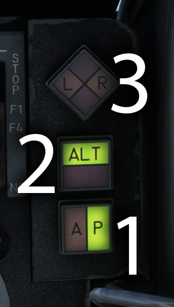
| # | Description | # | Description |
|---|---|---|---|
| 1 | Master autopilot button (basic mode) | 3 | Test button |
| 2 | Altitude mode button (advanced mode) |
The pilot can engage or disengage the autopilot using the "PA" button. This button can be illuminated with two colors:
-
Green when autopilot is engaged.
-
Amber, blinking for three seconds, when autopilot is disengaged.
Once master button is pushed, autopilot is powered and current heading will be automatically maintained.
“ALT” button will toggle altitude hold mode, and set the target altitude to the current aircraft altitude. This button can be illuminated with two colors:
-
Green when altitude hold is active.
-
Red, blinking for three seconds, when altitude hold is disabled.
Test button is divided in four distinct zones:
-
“L” and “R” are illuminated (amber) if roll trim is not centered.
-
Red zones are illuminated to indicate pitch trim or roll trim failure.
If you wish to use vertical speed mode (V/S mode) in order to change altitude, or change current target heading, you can do it from the dedicated tab on the EFB tablet.
Radio altimeter
Mounted on the instruments panel, the indicator shows radar altitude, from 0 to 2500 feet, with a logarithmic scale from 500 feet.
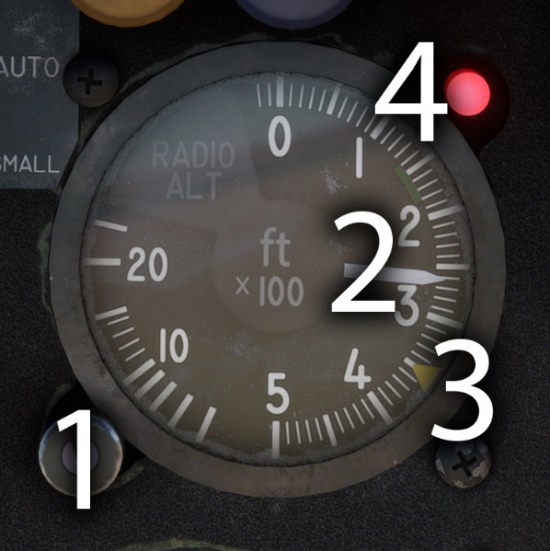
| # | Description | # | Description |
|---|---|---|---|
| 1 | Height selection and test (on press) | 3 | Selected height (index) |
| 2 | Radio height needle | 4 | Warning light |
In normal conditions, warning light is on when aircraft is losing altitude and is between 0 and 200 ft below the height set.
Control knob can be pressed (right click) in order to test the equipment: needle should go in the green sector (140 to 180 ft) and red warning light should be on.
If the aircraft has too much bank angle or pitch, the indicator will go to zero and the failure flag will appear, as the equipment cannot measure the height in those conditions.
Clock
The clock is located just above angle of attack indicator and was extensively used by pilots during navigation. It serves a dual purpose as both a clock and a chronometer.
The two larger hands indicate the current time (hours and minutes). The central second hand shows the seconds counted by the chronometer, while the small subdial at the bottom indicates the elapsed minutes.
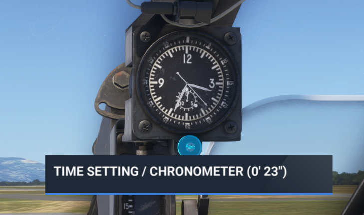
It is controlled with a single button:
-
Left click allows to set hour and minutes and will affect the time in the simulator.
-
Right click allows to start and stop the chronometer. A long right click will reset the chronometer.