Hydraulics
Description
The onboard hydraulic system powers the following components:
-
Flight controls and auto-stabilization.
-
Flaps and leading-edge slats.
-
Airbrakes.
-
Landing gear.
-
Nose wheel steering and anti-shimmy system.
-
Brakes.
-
Refueling probe.
The system consists of two circuits, identified as circuit 1 and circuit 2. Each circuit is pressurized by a pump driven by the accessory gearbox, respectively on left and right engine.
In case of pressure loss in one of both circuits, a power transfer unit transfers hydraulic power (without fluid transfer) from the operational circuit to the failed circuit. This ensures normal operation of all hydraulic components, even in the case of a single engine loss for example.
Each circuit includes a pressurized reservoir, a cooling system using fuel as a heat exchanger, an accumulator to dampen pressure fluctuations, and a bypass valve to offload the pump during engine start or ventilation.
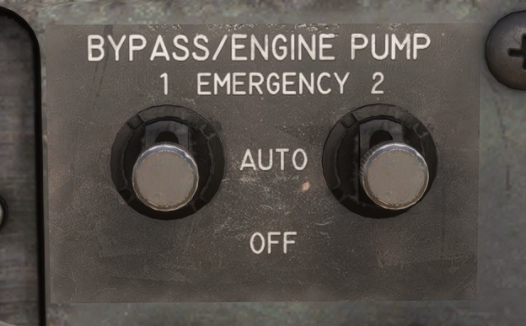
Hydraulic power transfer
Power transfer is managed by two switches (one per circuit), controlling by-pass valves with three operating modes:
By-pass in "OFF" Mode
-
By-pass valve is closed.
-
No hydraulic power is transferred.
Bypass in "AUTO" Mode
- By-pass valve of the motor-pump is controlled by a tachometric switch of the opposite generator, automatically engaging the motor-pump when an engine shuts down.
For example, if left engine is shut down:
-
Generation 1 by-pass valve opens.
-
The electro valve opens, supplying the motor-pump with pressure from generation 2.
-
The motor-pump operates as a motor on generation 2 and as a pump on generation 1.
During engine start, with by-pass selectors in "AUTO" position, the motor-pump of the circuit corresponding to the engine being started will be functioning as soon as 42% RPM is reached, providing hydraulic power to the other circuit.
Bypass in "RESC" (EMERGENCY) Mode
-
By-pass valve is always opened.
-
Motor-pump permanently engaged.
To recap, here is the table of hydraulic pressures for different scenarios:
| Scenario | Circuit 1 ("HYD1") | Circuit 2 ("HYD2") | Circuit 2 (electrical pump) |
|---|---|---|---|
| Normal (no flow) | 206 bars | 206 bars | 150 bars |
| Warning light ON/OFF | ~100 bars | ~100 bars | |
| Circuit 1 powered by motor-pump | 180 bars | 206 bars | |
| Circuit 2 powered by motor-pump | 206 bars | 180 bars |
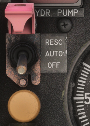
Electrical pump
A backup electric pump supplies pressure in case of failure of both engine-driven pumps. It ensures emergency operation of key systems such as flaps, airbrakes, landing gear extension, brakes, etc. The electric pump operates at 150 bars and delivers 8.5 L/min. It is controlled via a three-positions switch:
-
OFF: pump off.
-
AUTO: automatic activation when pressure drops below 100 bars in both circuits.
-
RESC: pump always on.
Electro-pump is monitored through an amber light located just below the switch. The light is on if the pump is functioning.
Landing gear
The landing gear is tricycle-type, with a steerable nose wheel. The main landing gear features twin wheels, and retracts obliquely forward and stows flat under the fuselage. The auxiliary single-wheel gear retracts from front to rear.
The landing gear track width is 2.40 m, and the wheelbase is 5.70 m.
Under normal operation, landing gear actuation is electro-hydraulically controlled.
An emergency system allows for door opening and landing gear extension.
Current landing gear state is indicated in the dedicated panel:
-
One green light for each gear, illuminated if gear is down and locked.
-
A single red light indicating a non-locked landing gear.
Landing gear should not be extended above 250 knots to avoid any damage.
Steering
Nose wheel steering is enabled by default and requires hydraulic power to function. The nose wheel can be steered via the rudder pedals, with a maximum deflection of ±55°.
A button on the left side of the yoke is used to toggle steering. You can also use the control binding STEERING INC.
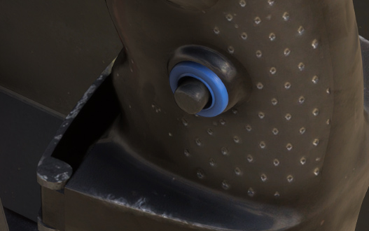
Active steering wheel is indicated with an amber light on instruments panel:
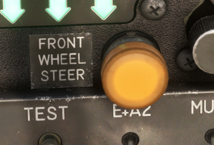
When the aircraft is empty, with steering engaged, the minimum turning radius is 7.10 m.
Flaps and slats
High-lift system is composed of:
-
Leading-edge slats (one per wing).
-
Double-slotted flaps (two per wing).
Both the slats and flaps are operated by electro-hydraulic controls.
Flap control is managed via a lever on the left side console, with five selectable positions:
0° - 5° - 10° - 20° - 40°
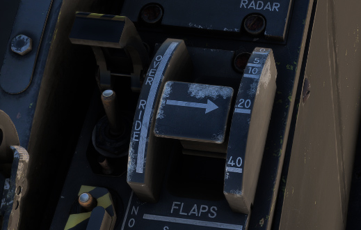
An emergency “override” switch allows flap extension even in case of a slat deployment failure.
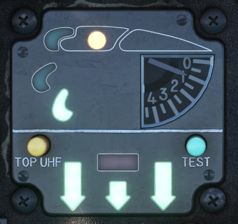
Flaps and slats state is indicated on the dedicated panel:
-
A round amber light indicates extended flaps (at least its first position).
-
Three green lights indicate current slats angle (see details here).
-
A needle shows current flaps angle, from 0 to 40 degrees.
Slats operation
A cambered slat is mounted on the leading edge of each wing. Three steel rails, fixed to the slats, are guided by rollers mounted on the wing's leading edge.
The slats are driven by four screw jacks (two per slat), interconnected by torsion shafts. The entire transmission system is housed within the wing, ahead of the main wing box.
The slats have three positions (as indicated on the panel):
-
Fully retracted.
-
Combat position, automatic position when flying at high angle of attack.
-
Fully extended, position when flaps are extended (at any position).
Slats are extended automatically below 500 knots, when angle of attack is higher than 6 degrees, and retracted when angle of attack goes below 5 degrees.
Slats can be toggled to manual mode by pressing the following button, which will be illuminated (white):

In manual mode, slats are controlled by a switch on left console (extended – neutral – retracted).
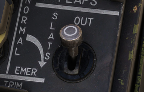
Above 500 knots, slats cannot be extended any more, and can only be retracted.
Airbrakes
The airbrakes are located on both sides of the fuselage, behind the main landing gear doors.
Each airbrake is operated by a hydraulic actuator and is locked in the retracted position by a latching mechanism.
The hydraulic pressure used is supplied by HYD 2 circuit.
The airbrakes are controlled by a toggle switch located at the end of the right engine throttle lever:
The airbrakes remain hydraulically locked in any intermediate position or at full extension. The full extension or retraction time on the ground is approximately 3 seconds.
An indicator light on instruments panel informs the pilot of their status:
-
Illuminated: airbrakes unlocked.
-
Off: airbrakes fully retracted and locked.

The operation of airbrakes is stopped automatically when the APU is running, as they must remain open to keep the exhaust clear.
Refueling probe
The Jaguar A can be air-to-air refueled via a retractable probe located on the right side of the fuselage, forward of the cockpit.
When retracted, the probe is housed in a recess on the fuselage side, covered by a closing door.
The probe deployment and refueling operation are controlled by the air-to-air refueling selector, with four positions:
-
EMERG: probe extended using emergency circuit.
-
IN: probe retracted using normal circuit.
-
OUT: probe extended using normal circuit.
-
REFUEL: with probe extended, position to begin refueling.
The probe's status is indicated by indicator lights located next to the selector:
-
Red light illuminated when probe is moving.
-
Green light illuminated when aircraft is ready for refueling.

The air-to-air refueling probe features a tip equipped with a backup self-sealing valve.
The probe assembly is mounted on a probe arm, which is attached to a swivel joint and connected to the probe actuator.

Brakes
The JAGUAR is equipped with an anti-skid system (SPAD) that maximizes the efficiency of the aircraft's mechanical braking system.
Brakes are hydraulically fed by circuit 1, and circuit 2 in case of emergency.
Normal brakes are triggered by pressing rudder pedals.
In case of emergency or to keep the aircraft parked, a handle is located in front of right console: