Electrical system
Description
Electrical power is produced by two main circuits:
-
A/C three-phase network, composed of two buses supplied by two alternators (one per engine).
-
D/C network, supplied by A/C buses with two rectifiers. A 24 V battery, nickel-cadmium with a 40 Ah capacity, is used to power this network when both engines are off and alternators are not providing any power.
A/C power generation
The primary 115/200 V, 400 Hz network is supplied by the alternators, which independently feed their respective distribution bars:
-
The left alternator powers bus 1.
-
The right alternator powers bus 2.
In addition to the various loads connected to these buses, bus 2 also supplies 115 V and 26 V buses.
If one alternator fails, buses 1 and 2 are automatically connected, and the remaining alternator takes over the load.
The alternators are three-phase 115/200 V, 400 Hz, 12 kVA alternators. Each one is driven by the accessory drive gearbox of the corresponding engine. It consists of an electromechanical variable-speed drive, which maintains a constant alternator speed for input speeds ranging from 3,800 to 8,000 RPM. This ensures that the generated current frequency remains stable at 400 Hz ± 1%.
D/C power generation
The 28 V D/C power is obtained from two transformer-rectifiers, which are powered by A/C distribution buses 1 and 2. The transformer-rectifiers operate in parallel, supplying the distribution buses, which are connected through a contactor controlled by the protection system.
The battery, acting as a buffer, continuously supplies the battery bus. This 40 Ah nickel-cadmium alkaline battery serves as the ultimate reserve of electrical energy in the event of a failure of both variable alternators.
Under normal operation, it is connected to the D/C distribution buses through a circuit breaker contactor. It continuously supplies the "battery" distribution bus and, in the event of a failure of both alternators, it powers the 28/115 V static converter and the emergency DC bus 2.
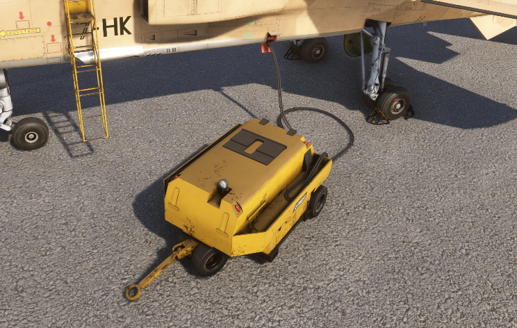
Ground power
Ground power unit can be selected on the EFB to relieve the battery when aircraft is on ground with both engines off. It is connected on a socket in front of the left gear strut.
Lights
Exterior
The following exterior lights exist on the Jaguar:
-
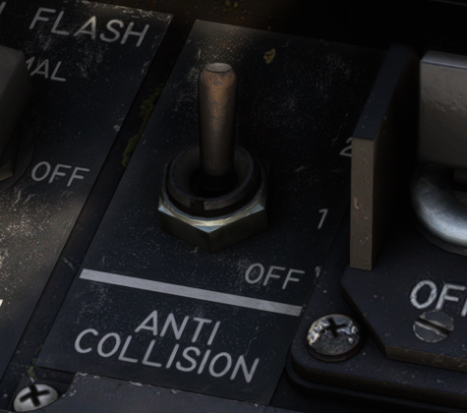
Anticollision (beacon) lights.
-
Navigation lights.
-
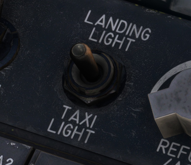
Taxi light.
-
Landing light.
-
Formation lights (lights on top of wings, used during formation flying).
-
Refueling lights (two side lights placed to illuminate refueling probe).
Two beacon lights (top of fuselage & belly) can be powered independently from the same switch on left console:
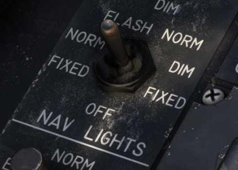
Navigation lights can be set to four different settings:
-
Off.
-
Fixed with normal intensity.
-
Fixed with dimmed intensity.
-
Flashing.
This switch is moved with left click maintained and drag in the desired position.
A common switch (located in front of throttles) is used to manage taxi and landing lights. When landing gear is retracted, those lights are turned off automatically.
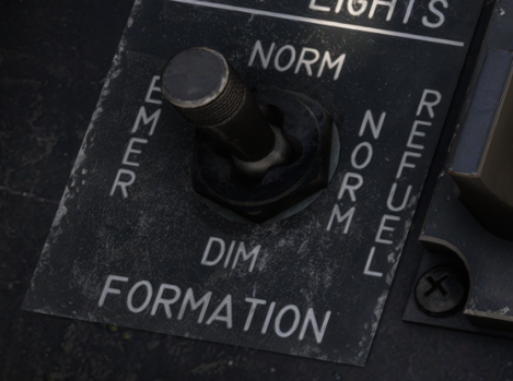
Formation lights and refueling lights are managed with a common switch with five positions:
-
OFF.
-
NORM: formation lights with full intensity, refueling lights off.
-
DIM: formation lights with dimmed intensity, refueling lights off.
-
REFUEL NORM: formation lights with normal intensity, refueling lights on.
-
EMERGENCY: formation lights off, refueling lights on and forced to maximum intensity.
This switch is moved with left click maintained and drag in the desired position.
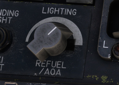
A knob allows to set refueling lights intensity. This same knob also commands intensity of AoA indicator light.
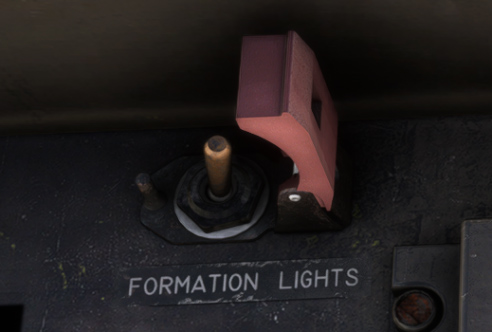
By default, refueling lights cannot be used if refueling probe is retracted. A switch behind a hood is used to force refueling lights even in that case:
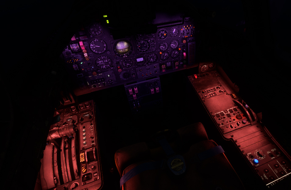
Interior
Interior lights are the following:
-
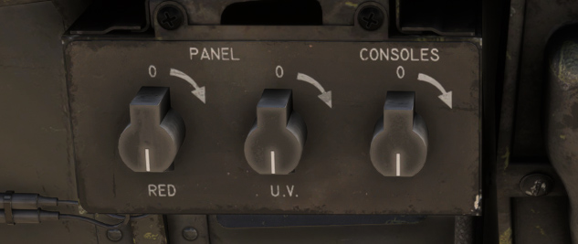
Panel lights (red and UV setting).
-
Console lights (red).
-
Integrated lights (white backlighting, for both consoles).
-
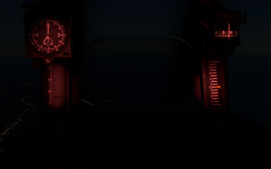
Instruments lights (red).
-
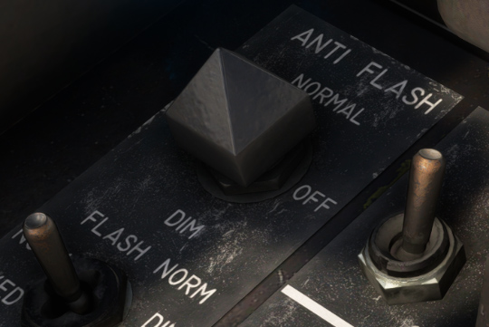
Anti-flash lights (white).
They are made to fly in any conditions, including night.
Panel and console lights can be set at different intensities with three knobs above right console. For instruments panel, red lights or UV lights (or a mix of both) can be chosen.
Integrated lights can be set at different intensities, independently for left and right side of the cockpit (left console):
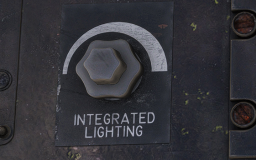
Please note that integrated lights will also manage backlighting of the GPS units.
Instruments lights are powered with a knob located below the clock:

This light is dedicated to the instruments located above the panel: clock, standby compass, angle of attack indicator and accelerometer.
Anti-flash lights can be set on two different settings (normal or dim) and are illuminating instruments panel with a strong white light:
Alarms
Several alarms (visual and aural) to indicate any abnormal event to the pilot.
Those alarms are divided into different categories:
-
Warning (red light).
-
Caution (amber light).
-
Other alarms.
In order to avoid any alarm indication failure, each alarm is using two lights connected in parallel.
Alarms panel
Alarms panel is located on bottom left part of instruments panel. It gathers all main alarms (warning and caution).
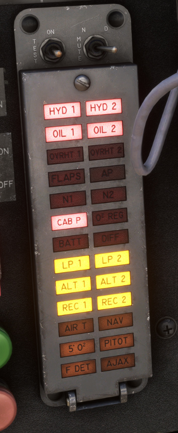
Any warning alarm will also trigger master warning alarm (blinking light and alert sound).
Two switches are located above alarms panel:
-
First switch is used to toggle between three modes:
-
TEST: Test lights, alarms and master warning.
-
All alarms of the panel.
-
Fire indication lights.
-
Master warning light.
-
Master warning sound.
-
Landing gear lever light.
-
Fuel panel amber lights.
-
APU starter button light.
-
-
ON: Normal detection mode.
-
MUTE: Alarms are ignored and sound is muted, but master caution light stays on.
-
-
Second switch has two positions (DAY and NIGHT) to toggle between two light intensities, for alarms lights but also for the other lights mentionned above.
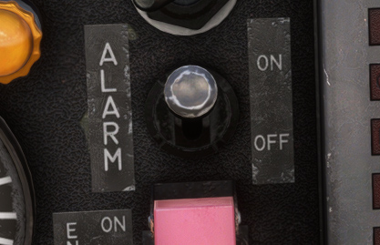
Alarm sound switch allows to mute alarms sound and should be used only in case of anomaly with the sounds:
Here is the description of each alarm of the panel:
| Alarm | Description | Alarm | Description |
|---|---|---|---|
| HYD 1 | Circuit 1 hydraulic pressure below 100 bars | HYD 2 | Circuit 2 hydraulic pressure below 100 bars |
| OIL 1 | Differential oil pressure (left) below 0.84 bars | OIL 2 | Differential oil pressure (right) below 0.84 bars |
| OVRHT 1 | Left engine cooling air above 400 °C | OVRHT 2 | Right engine cooling air above 400 °C |
| FLAPS | Flaps extended above 8° above 260 kts | AP | Autopilot failure |
| N1 | Fuel in N1 tank below 100 kg | N2 | Fuel in N2 tank below 100 kg |
| CAB P | Cabin pressure altitude above 27,000 ft or canopy not locked | O² REG | Zero oxygen flow |
| BATT | Battery disjunction | DIFF | Elevator differential deflection failure |
| LP 1 | Left engine fuel pressure below 2.4 bars | LP 2 | Right engine fuel pressure below 2.4 bars |
| ALT 1 | Left alternator disconnected | ALT 2 | Right alternator disconnected |
| REC 1 | Left rectifier disconnected | REC 2 | Right rectifier disconnected |
| AIR T | Air conditioning above 80 °C | NAV | Navigation calculator failure |
| 5’ O² | Oxygen reserve, pressure below 150 bars | PITOT | Pitot heat disabled |
| F DET | Fire detection failure | AJAX | AJAX failure |
For HYD1 and HYD2 alarms, only a simultaneous failure will trigger master warning, as both hydraulic circuits are redundant.
Other alarms
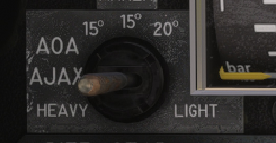
Angle of attack alarm is heard when aircraft is flying at high AoA. It will be triggered at 15° or 20° of AoA depending on AJAX gain switch position.
Landing gear alarm is triggered if gear is not extended with a speed below 220 kts and at least one engine below 90% RPM. A light located inside landing gear lever is blinking.
Fire alarms are triggered if a fire is detected in zone 1 or zone 2 of the engines, they are described here.