Engines and auxiliary power
Engines
The Rolls-Royce Turbomeca Adour is a two-shaft, low bypass, twin-spool turbofan engine.
The Jaguar A and early GR1 versions were equipped with the Mk.102 version, which features an afterburner.
This engine has the following specifications:
| Max dry thrust | 5,160 lbf / 2,295 daN |
| Minimum afterburner thrust | 6,700 lbf / 2,980 daN |
| Maximum afterburner thrust | 7,380 lbf / 3,285 daN |
| Main characteristics | |
| Engine weight | 1,667 lbs / 756 kg |
| Bypass ratio | 0.85 |
| Total airflow | 92 lbs/sec / 41.7 kg/sec |
| Low-pressure compression ratio | 2.6 |
| Overall compression ratio | 9.6 |
| Low pressure spool speed | 13,600 RPM at 100% N1 |
| High pressure spool speed | 15,510 RPM at 100% N1 |
| Rotation direction | Counter-clockwise (rear view) |
| Ambient temperature impact | 10% thrust loss between +18 °C and +30 °C |
| Bleed air impact | Approx. 3% thrust reduction per engine |
| Fuel consumption | |
| Max dry fuel flow | 72 lbs/min / 32.6 kg/min |
| Max afterburner fuel flow | 265 lbs/min / 120 kg/min |
Each engine is housed in a dedicated compartment on either side of the central fuselage beam. A fireproof bulkhead divides each compartment into two sections:
-
Zone 1, which contains the core engine.
-
Zone 2, which includes the afterburner duct and exhaust nozzle.
Both zones are equipped with fire detection systems, but only zone 1 has a fire suppression system.
The original engine has a special feature called modulated afterburner, allowing to use reheat before the maximum dry thrust position. This feature is not simulated as the simulator does not support it.
Also, the “thrust increase” feature used for take-off in high-temperature (3-9% thrust increase) is not simulated.
Throttle
The engines are controlled by two throttle levers positioned on the left console. Each throttle lever controls the opening or closing of the high-pressure fuel valve of the corresponding engine, and allows thrust modulation with afterburner selection.
The range of motion for each throttle lever includes a dry thrust section and an afterburner section, with the following key positions from aft to forward:
-
Engine shutoff (HP fuel valve closed).
-
Idle (or start position).
-
Full dry thrust.
-
Minimum afterburner.
-
Maximum afterburner.
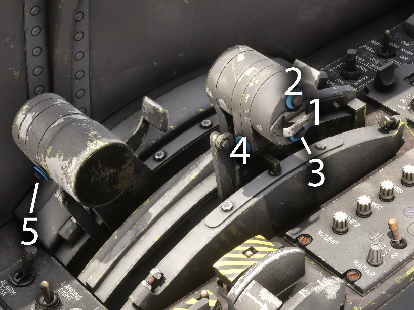
| # | Description | # | Description |
|---|---|---|---|
| 1 | Spoilers switch | 4 | Right engine restart button |
| 2 | Flares fire button (INOP) | 5 | Left engine restart button |
| 3 | Flares fire button (INOP) |
When operating the throttles with mouse in Flight Simulator, you need to maintain the throttle (left click) and do a right click to trigger shutoff and afterburner positions.
You can also bind your controller to trigger afterburner using a button (see controls options menu).
There is no existing binding in the simulator to go to fuel cut-off position. If you are using an external binding software (like FSUIPC), you can reach this position using the following B events: B:ENGINE_Throttle_1_Idle and B:ENGINE_Throttle_2_Idle (for left and right engine respectively).
Shutoff position
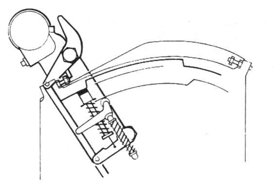
The throttle lever is in the fully aft position. The retractable stop override paddle is in the raised position, and the fixed stop on the lever arm rests against the rear stop of the housing. This position allows to shut down the engine.
Idle/start position
Push the throttle lever forward until the retractable stop, actuated by its spring, engages in the dry detent ramp and rests against the rear notch of this ramp. The stop paddle returns to the lowered position.
Maximum dry thrust position
Starting from idle, push the throttle lever forward until the retractable stop engages with the forward notch (full dry thrust) of the dry ramp.
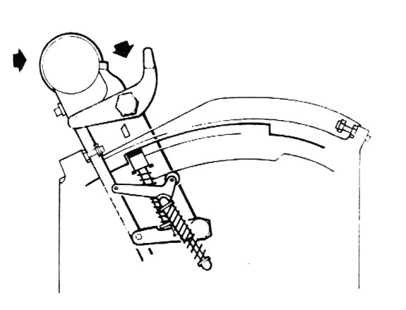
Afterburner ignition and maximum afterburner position
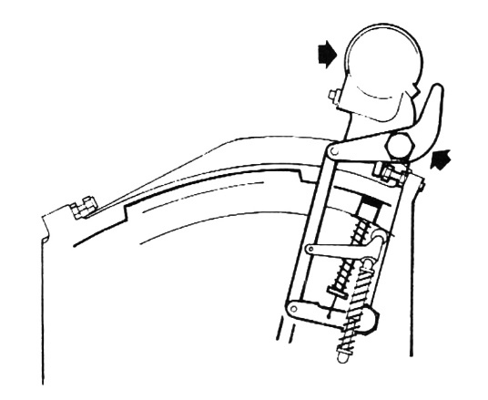
To pass the full dry thrust notch, operate the paddle (set it to the raised position). The retractable stop disengages, allowing the throttle lever to move into the afterburner range until the fixed stop on the throttle rests against the forward stop of the housing.
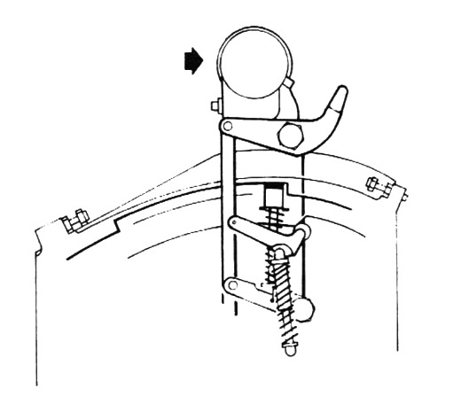
Throttle lever return to minimum afterburner stop
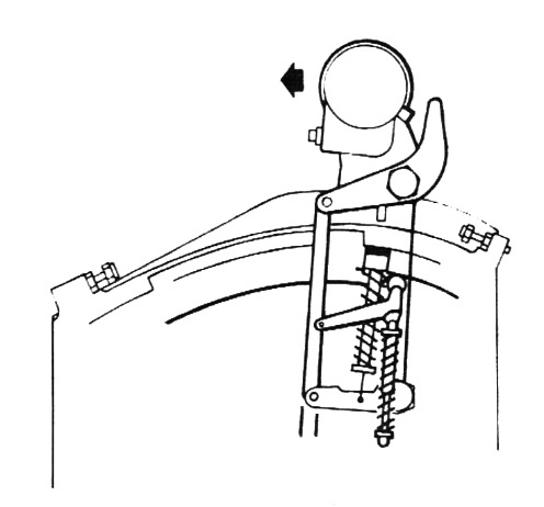
From the maximum afterburner position, pull the throttle lever back until the roller on the pivoting support rests against the notch of the lower afterburner ramp.
Afterburner cutoff
Move the throttle lever rearward into the dry thrust range. This maneuver involves:
-
Passing the minimum afterburner notch with the pivot support roller.
-
Releasing the retractable stop, which returns to the dry ramp after clearing the full dry thrust notch.
-
The stop override paddle returning to the lowered position.
-
The throttle lever can then be pulled back to the idle position.
Throttle lever return to engine shutoff position
Operate the stop override paddle (set it to the raised position) to lower the retractable stop, then pull the throttle lever back until the fixed stop on the lever arm rests against the rear stop of the housing (position 1 – engine shutoff).
Exterior components
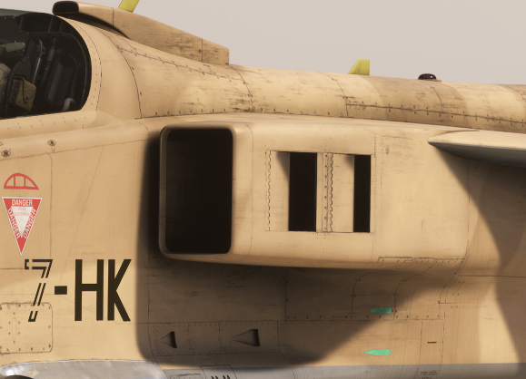
Intake flaps
The air intake ramps, part of the propulsion system, each have two air inlets doors on the sides, designed to improve engine airflow at low speeds.
Their operation is automatic, depending on the air pressure/vacuum at the engine intake. At idle on the ground, it is normal for the flaps to open slightly, while at high speeds, they will fully close to optimize airflow.
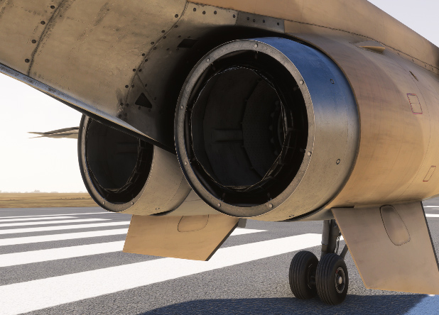
Variable position nozzle
The variable-area nozzle is controlled by overlapping flaps, connected to a command ring via rollers. Four actuators, powered by high-pressure fuel, adjust the nozzle opening.
In dry thrust mode, the flaps remain closed. When the afterburner is engaged, their position varies between partially open and fully open to maintain optimal exhaust pressure and ensure the turbine operates within safe detachment limits.
A sensor provides an electrical signal to indicate the nozzle position.
Auxiliary power
The Jaguar has an auxiliary power unit (APU) in order to provide compressed air for engine starting. This small gas turbine is located in the left airbrake compartment and is called “Microturbo”.
This turbine can only be powered with the airbrakes deployed. For this reason, airbrakes are usually extended before shutting down the engines, in order to facilitate the next start.
The fuel feeding the APU is collected at the upstream of right engine low-pressure valve.
The APU can be stopped manually or automatically in the following scenarios:
-
Startup takes more than 20 seconds.
-
It has been running for more than 10 minutes.
-
Both engines are started (RPM above 39% N1).
Engines operation
Startup
Startup is managed from the panel described here.
You must not forget to remove engine covers, which would prevent the engines from rotating, as described here.
With the airbrakes extended and the fuel feed and transfer pumps switch set to ON, APU master switch must be set to ON position, then the starter button should be pressed.
The APU starts and stabilizes at idle; generated bleed air is vented outside.
As specified in the previous section, airbrakes must be fully opened during ground start. A safety switch prevents the startup of the APU otherwise.
Setting the "START" selector to "ENGINE 1" (or "ENGINE 2") opens the air supply valve, allowing engine start. Simultaneously, the vent valve closes (the "VALVE OP" light illuminates). The air starter then drives the high-pressure spool, which induces airflow to start the low-pressure spool.
When the "CORRECT ROTATION" light turns on, meaning engine is rotating, throttle lever is moved to the ground start/idle detent.
Once the engine reaches the starter cutout speed (approximately 39% N1), the air supply valve closes and the vent valve reopens ("VALVE OPEN" light turns off). At the same time, the "CORRECT ROTATION" light goes off, and the igniters deactivate.
After the second engine start, APU shuts down automatically ("START" light turns off).
Monitoring
Several instruments in the cockpit are used to monitor the engines. In addition, several alarms are related to engines alerts.
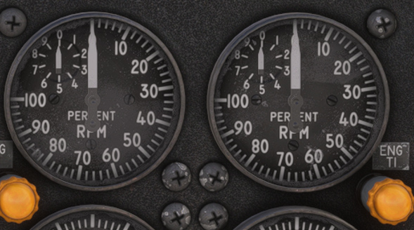
Tachometers
Each tachometer is powered by a tachometric generator and indicates the high-pressure spool rotational speed in %.
EGT Indicators
Each engine is equipped with seven thermocouple probes that measure the exhaust gas temperature downstream of the low-pressure turbine.
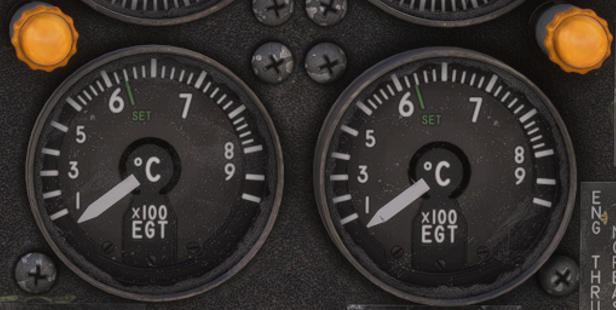
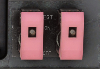
EGT amplifier switches can have an impact on the temperatures reached. On normal position (ON), it enables automatic regulation of the limit temperatures, and restricts the maximum speed of the low-pressure spool (by reducing fuel flow).
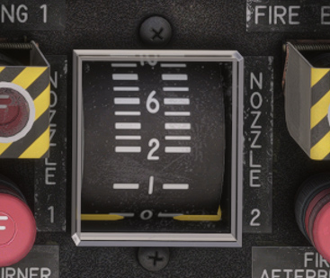
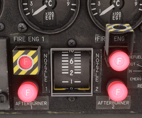
Nozzle position indicator
This indicator is graduated from 0 to 10 (no unit).
It allows to control the position of exhaust nozzle (left and right):
-
0 → idle to full dry thrust.
-
4 → minimum reheat.
-
6 to 8 → maximum reheat.
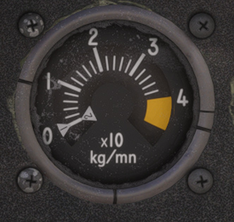
Fuel Flow indicator
This gauge indicates fuel flow for both engines:
-
Idle → around 3 kg/min.
-
Full dry thrust → around 30 kg/min, depending on conditions.
-
Afterburner → orange zone, more than 100 kg/min.
Indicator #2 also displays APU consumption (around 2 kg/min in normal conditions).
Fire
There are four independent fire detection circuits, one per zone (engine core, afterburner section) and per engine.
In case of hot gas leakage or fire, one of the detectors sends a signal to the control unit, which illuminates the corresponding fire warning light, triggers the audible alarm, and causes the master alarm light to flash.
Fire detection testing is performed using the TEST switch above alarms panel.
The extinguishing system includes:
-
A dual-head fire extinguisher bottle, equipped with two percussion cartridges.
-
Four distribution manifolds (two per engine), ensuring full saturation of zone 1 in case of fire. Each side is supplied by two pipelines connected to the extinguisher bottle.
-
Two percussion control buttons, concealed under covers, integrated into the fire warning lights of zone 1.
-
A crash bar, enabling simultaneous activation of both extinguishers.