Avionics
Our Transall is based on the C160R version, which has more complex avionics compared to previous versions, including screens instead of gauges.
We decided to develop full bespoke systems without re-using existing avionics from the simulator, hence several of them are not fully implemented yet and will be enhanced in future updates.
EFIS
Flight instrument system consists of two main screens for both pilot and copilot:
-
Electronic Attitude Director Indicator (EADI).
-
Electronic Horizontal Situation Indicator (EHSI).
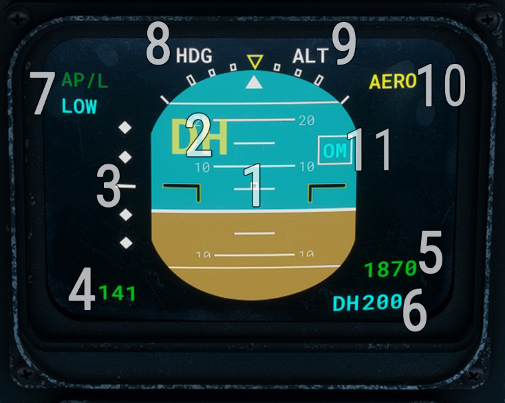
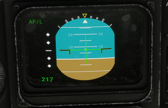
EADI
Primary screen displays general information about aircraft attitude and speed.
| # | Description | # | Description |
|---|---|---|---|
| 1 | Attitude | 7 | Autopilot state |
| 2 | Decision height reached indicator | 8 | Autopilot lateral mode |
| 3 | Glideslope deviation indicator | 9 | Autopilot vertical mode |
| 4 | Airspeed | 10 | Spoilers extended indicator |
| 5 | Radio altitude | 11 | ILS marker flag (outer/middle) |
| 6 | Decision height selection |
Radio altitude is displayed if it is below 2,500 ft, with an increment of 5 ft below 50 ft and 10 ft above.
If decision height is set with the associated DSP knob, indicator will appear once it is reached and will stay unless aircraft is landed or decision height is changed again.
“AP/L” inscription indicates that autopilot is managed by the pilot (only option available for now), and becomes green once autopilot master is on. “LOW” inscription is displayed below 160 knots to indicate a different operating mode where gains on commands amplifiers are reduced (on the three axis).
On top of the screen, current autopilot mode is displayed.
Possible lateral modes are:
-
“HDG” for heading selection mode.
-
“ROLL” for bank angle hold mode.
-
“LOC1”/”LOC2” for localizer capture mode (ILS approach) on NAV1/NAV2.
Possible vertical modes are:
-
“ALT” for altitude hold mode.
-
“GS1”/“GS2” for ILS glideslope capture mode on NAV1/NAV2.
-
“FMS1” for FMS or GPS trajectory mode.
-
“TCN” for TACAN radial following mode.
-
“VOR1”/”VOR2” for VOR radial following mode on NAV1/NAV2.
Once a mode is captured (trajectory locked), its text switches from white to green color.

EHSI
Secondary screen is based around a central rose indicating aircraft heading, and information related to radionavigation and flight plan navigation.
EHSI has three different possible displays: HSI, ARC and MAP.
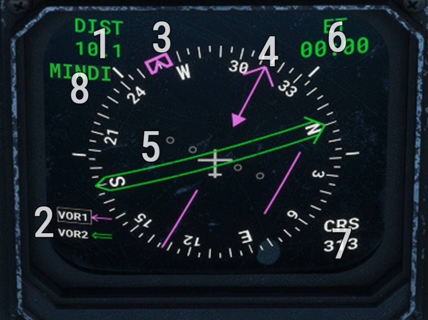
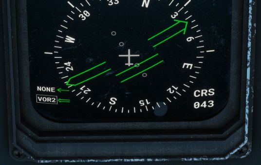
HSI mode
| # | Description | # | Description |
|---|---|---|---|
| 1 | Distance to station | 5 | Double arrow indication |
| 2 | Navigation sources and active one | 6 | Dynamic data display zone |
| 3 | Heading reference bug | 7 | Course selected for active source |
| 4 | Single arrow indication | 8 | Next flight plan waypoint ident |
Single arrow can display VOR1 course (with deviation), ADF station direction or FMS1/GPS next waypoint direction.
Double arrow can display whether VOR2 course or TACAN course, with deviation.
Current source selected for CRS selection and distance display is indicated by a small white border.
By default, arrows are hidden and “NONE” is displayed as active sources.

Heading reference bug represents target heading and will be used by the autopilot when it is running in heading selection mode.
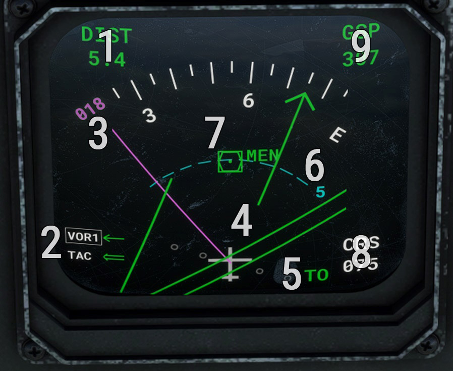
ARC mode
| # | Description | # | Description |
|---|---|---|---|
| 1 | Distance to station | 6 | Map range |
| 2 | Navigation sources and active one | 7 | VOR/ADF/TAC/waypoint position |
| 3 | Heading reference/target | 8 | Course selected for active source |
| 4 | Single and double arrows indication | 9 | Dynamic data display zone |
| 5 | TO/FROM flag |
In ARC mode, main difference is that background corresponds to a map with range, showing the position of VOR/ADF/TACAN beacon or next FMS/GPS waypoint, depending on active navigation source.
When heading reference/target is outside of displayed arc angle, its value is written on the sides.
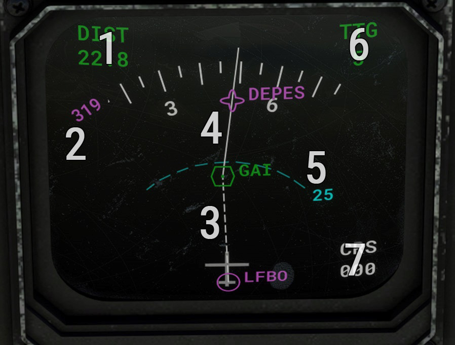
MAP mode
| # | Description | # | Description |
|---|---|---|---|
| 1 | Distance to station | 5 | Map range |
| 2 | Heading reference/target | 6 | Dynamic data display zone |
| 3 | Flight plan active segment | 7 | Course selected for active source |
| 4 | Flight plan route and waypoints |
In MAP mode, only flight plan is displayed with departure airport, all its waypoints and arrival airport.
Map range can be changed to display a bigger part of the flight plan.
It is important to ensure IRS is switched on and aligned in order to see flight plan correctly.
Dynamic data display zone
Top right zone data to display can be changed with DSP data display knob as described in next subsection.
- Option 1
- Option 2
- Option 3
- Option 4
Wind speed and direction (relative to aircraft).

Ground speed.

Time to goal (estimated time to reach next flight plan waypoint).

Chronometer/countdown.

Display selector panel
EFIS commands are gathered on Display Selector Panel (DSP).
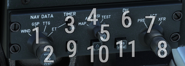
| # | Description | # | Description |
|---|---|---|---|
| 1 | EHSI data display knob | 7 | Active course selection knob (inoperative) |
| 2 | Change heading target reference (rotation) Set heading target to current heading (click) | 8 | Set navigation OBS (rotation) Set direct-to course (click) |
| 3 | Set countdown duration (rotation) Start/stop chronometer or countdown (short click) Reset chronometer (long click) | 9 | Set single needle source (NONE, VOR1, ADF or FMS1) |
| 4 | EHSI rose display mode knob | 10 | Set double needle source (NONE, VOR2 or TACAN) |
| 5 | EHSI range selection knob | 11 | Toggle active navigation source |
| 6 | Decision height setting knob |
Another more accessible button allows to start and stop chronometer on both pilot and copilot sides:

IRS
Inertial Reference System (IRS) relies on several internal and external sensors to elaborate several information needed to fly the aircraft, like attitude, angular velocities, accelerations, ground speed, position.
Two of them are disposed in our aircraft and are redundant. They should be running at any time during the flight.
IRS is functioning when the knob is on “NAV” position, after which an initialization sequence of approximately 30 seconds will take place. A parallel GPS system allows to determine initial position, and IRS is able to know aircraft position at any time from that point.
Four orange lights can be displayed:
-
“ALIGN MODE”: IRS in alignement mode.
-
“BAT OPER”: generators not proving any current, electricity supplied by the batteries.
-
“BAT WARN”: batteries not able to ensure correct function of the IRS.
-
“IRS WARN”: IRS malfunction.

“ATT” is a test position which is not simulated.
FMS
Flight management system has been added in modern C-160 versions (NG) to manage everything related to radio and flight navigation. It is linked to all other aircraft systems (EFIS, autopilot, etc).
Our Transall does not have 100% of its original functionalities but everything needed to navigate with a flight plan.
Both FMS units (pilot and copilot) allow to achieve the same actions.
Do not forget to switch IRS on in order to be able to use all functionalities.
Overview
Generic structure of an FMS page is the following:
-
Top status line.
-
One title line.
-
Eight lines with dynamic data depending on the active page.
-
One line for current keyboard entry.
-
A bottom line with five potential actions.
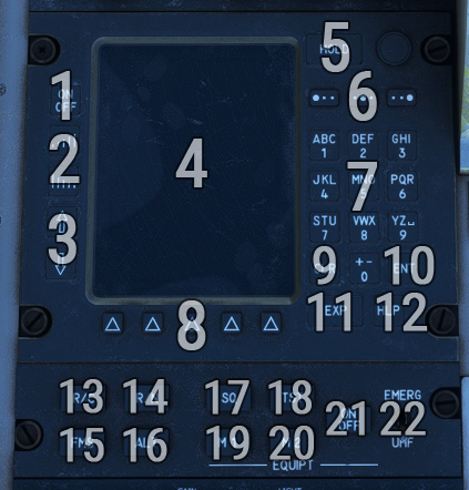
| # | Description | # | Description |
|---|---|---|---|
| 1 | Power button (hold to turn off) | 12 | Help button |
| 2 | Screen brightness buttons | 13 | Radiocommunication page |
| 3 | Line pointer change button | 14 | Radionavigation page |
| 4 | Screen | 15 | Leave FMS mode |
| 5 | Hold button | 16 | Altitude page |
| 6 | Letter selection button | 17 | Mute selected equipment |
| 7 | Keyboard | 18 | Test selected equipment |
| 8 | Variable label keys | 19 | Equipment mode 1 |
| 9 | Clear button | 20 | Equipment mode 2 |
| 10 | Enter button | 21 | Turn selected equipment on/off |
| 11 | Expand button | 22 | UHF emergency frequency |
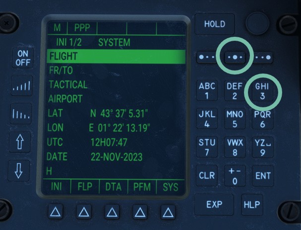
Ten keys allow to write any digit between 0 and 9 from the keyboard.
In order to write any letter, you first need to click on the corresponding key where this letter appears, and then to choose one of the three letter selection buttons (above keyboard) depending on the position of the letter you want to write on its key.
In the following example, letter “H“ is entered:
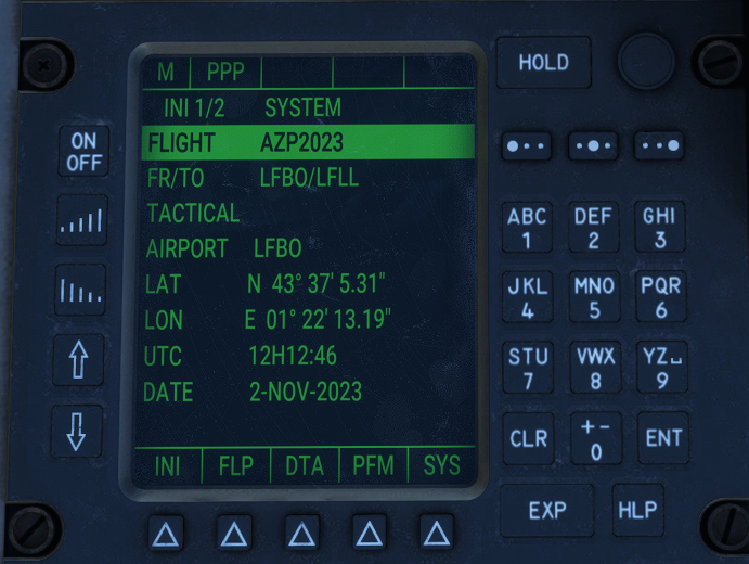
INIT1 page
After FMS is started, INIT1 is the first page displayed.
Once IRS is aligned, initialization coordinates are displayed. They cannot be entered manually.
Flight number can be entered on the first line (free format).
Second line displays departure and arrival airports (OACI code), that can be changed to begin a new a flight plan. To do this, put the cursor on this line, enter both OACI codes with the keyboard and click on ENT.
Fourth line shows departure airport and allows to access departure page.
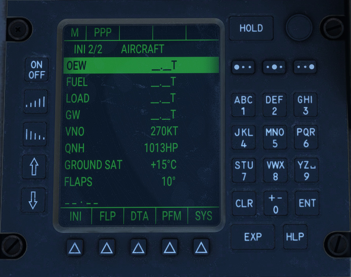
INIT2 page
By clicking again on first label key (INI), INIT2 page is displayed.
You can enter on first three lines (tons unit):
-
Aircraft empty weight.
-
Fuel weight.
-
Load weight.
Gross weight will be calculated automatically by summing those values.
You can also set local QNH, ground air temperature and flaps setting used for takeoff.
DEPARTURE page
To enter departure page, you need to select AIRPORT line on INIT1 page, and click on EXP.
Departure page shows airport ICAO, coordinates, elevation and longest runway length.
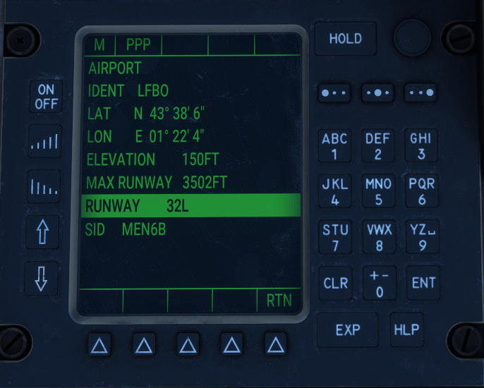
You have to select the departure before choosing any runway.
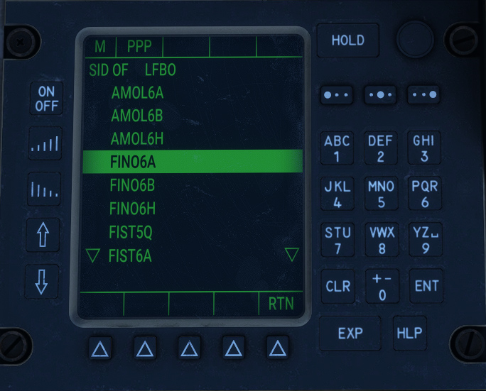
After selecting SID line and clicking on EXP, list of available standard instrument departures (SID) is displayed. You can select on with ENT button.
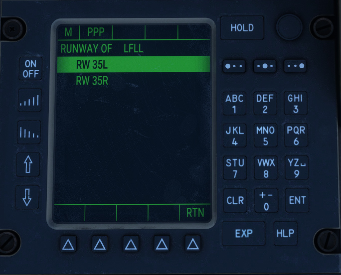
Only once departure procedure is selected, you can access runway page (with EXP button) and select departure runway from the list with ENT button.
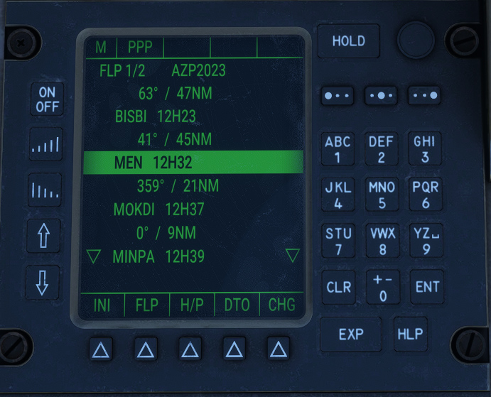
FLP1 page
FLP1 page contains flight plan waypoints list. Only next waypoints are displayed, and they are removed once reached.
It is accessed from INIT pages using FLP action button.
You can see for each waypoint:
-
Estimated time of arrival (ETA), depending on current ground speed.
-
Heading to the next waypoint.
-
Distance to next waypoint.
In order to reset the flight plan completely, do a long click on CLR button (with the cursor on any line).
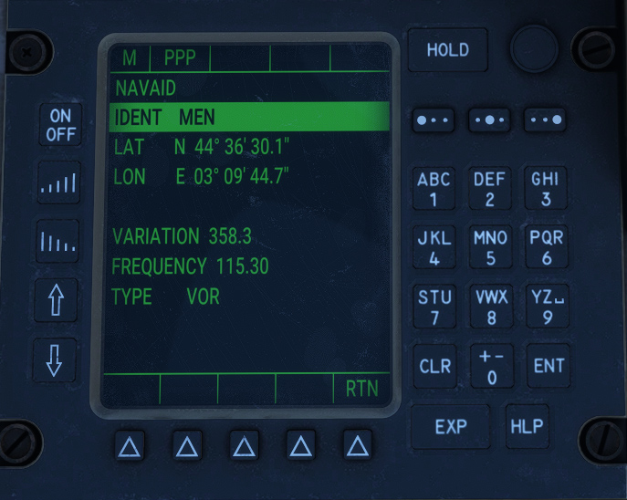
FACILITY page
After selecting any waypoint on FLP1 page, you can access facility page with EXP button.
This page shows waypoint coordinates, plus magnetic variation and frequency if the waypoint is a VOR.
You can exit the page with RTN action button.
ARRIVAL page
To access arrival page, you need to click on EXP button after having selected arrival airport on FLP1 page (which is the last waypoint of the list).
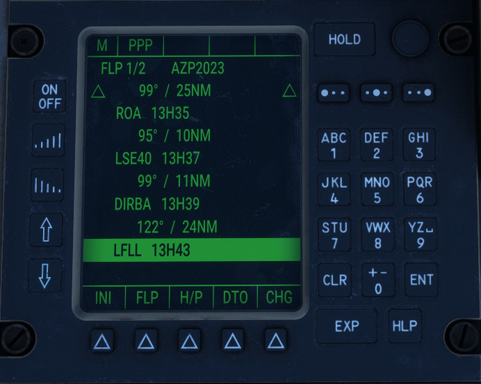
You can then select standard instrument arrival (STAR) and runway as you would select a SID and a runway on departure page.
You have to select the arrival before choosing any runway.
As weird as it may seem, Transall FMS does not allow to set an approach (ILS, etc), you need to manage it manually.
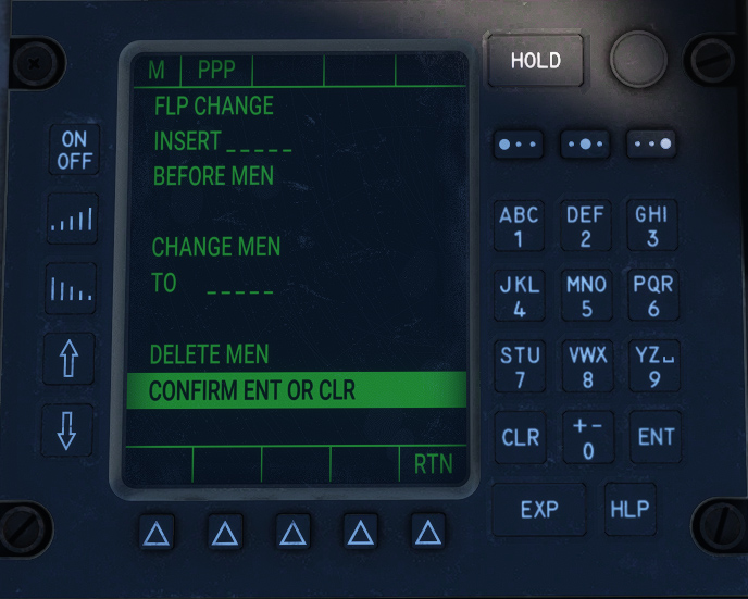
FLP CHANGE page
This page is the only place to edit the flight plan.
After selecting a waypoint on FLP1 page, you need to click on CHG action button.
From there are three possible actions:
-
Entering a new waypoint to be inserted before selected waypoint.
-
Change selected waypoint to another waypoint.
-
Delete selected waypoint.
After selecting one of these actions with ENT button, you will need to click ENT a second time to confirm.
Once action is submitted, FLP1 page is displayed again.
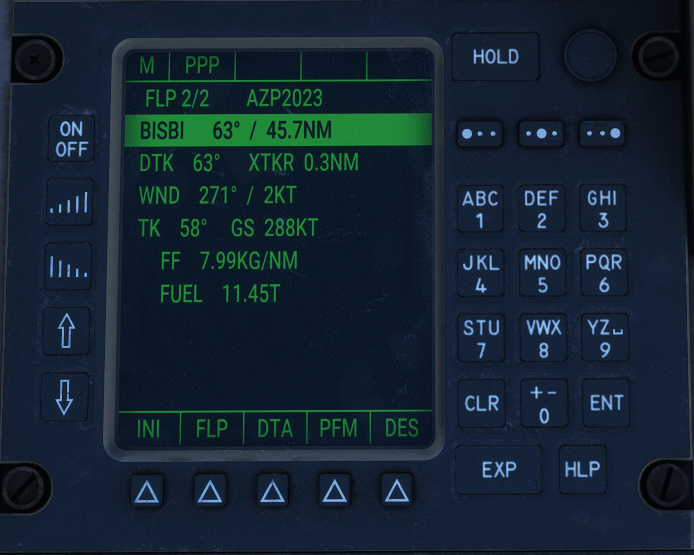
FLP2 page
When clicking on FLP action button, FLP2 page is displayed with information related to next goal:
-
Ident of the waypoint.
-
Straight heading to the waypoint.
-
Current distance between aircraft and waypoint.
-
Heading to follow desired track (DTK), which is the line between previous and next waypoint.
-
Cross track distance (XTKR) representing deviation from desired track.
-
Current wind (direction and velocity).
-
Current GPS track.
-
Current ground speed.
-
Current fuel flow (kilograms per nm).
-
Total remaining fuel (tons).
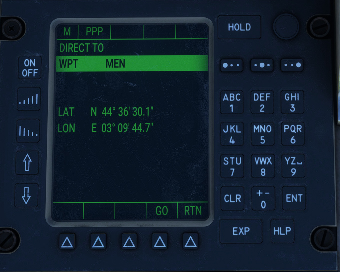
DIRECT TO page
This page allows to go directly to a specific waypoint of the flight plan by skipping all the previous waypoints.
You can access the page after selecting a waypoint on FLP1 page and clicking on DTO action button.
Clicking on GO action button will apply the modifications to the flight plan.
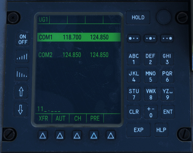
COM page
This page shows active and standby radiocommunication frequencies on channels 1 and 2.
To change a frequency:
-
Go to desired line with left pointer buttons.
-
Enter frequency with the keyboard (for example 11825). Frequency pattern is displayed in background of the current entry.
-
Click on ENT to change active frequency, or PRE to change standby frequency.
-
Select XFR action to switch standby and active frequencies.
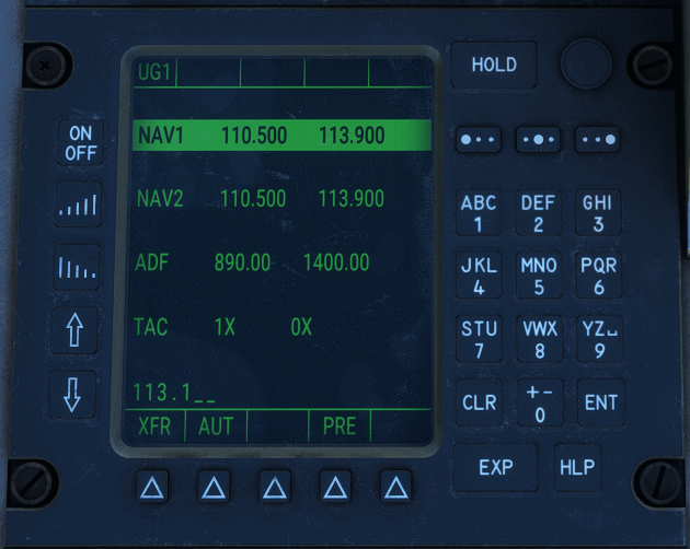
NAV page
This page shows active and standby radionavigation frequencies for NAV, ADF and TACAN.
To change a frequency:
-
Go to desired line with left pointer buttons.
-
Enter frequency (or TACAN channel) with the keyboard (for example 11050). Frequency pattern is displayed in background of the current entry.
-
Click on ENT to change active frequency, or PRE to change standby frequency.
-
Select XFR action to switch standby and active frequencies.
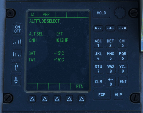
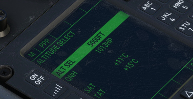
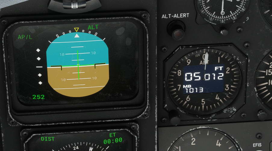
ALTITUDE page
This page allows to change target altitude for the autopilot, and barometric reference.
It also shows current Static Air Temperature (SAT) and Total Air Temperature (TAT).
Autopilot
Autopilot ensures aircraft stability around three axis (roll, pitch, yaw) without any manual actions needed on the controls.
As it is based on default autopilot implementation, you can bind any autopilot function to your controller (from controls options).
The following functions are covered by the system:
-
Current heading hold (HDG HOLD).
-
Selected heading interception and hold (HDG SEL).
-
Selected pitch hold (PITCH).
-
Selected bank angle hold (TURN).
-
Selected altitude interception and hold (ALT).
-
Radionavigation route interception and hold (RADIO), connected to NAV1, NAV2, TACAN and GPS.
Once master switch is on, heading and pitch hold are activated by default.
Bottom row of buttons has integrated lights that are on when the given function is activated.
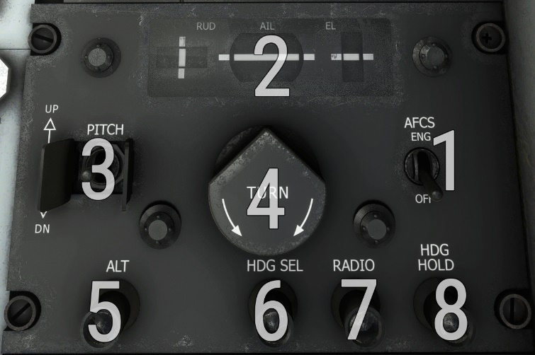
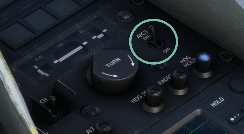
| # | Description | # | Description |
|---|---|---|---|
| 1 | Master autopilot switch | 5 | Altitude selection mode button and light |
| 2 | Flight director instruction bars (three axis) | 6 | Heading selection mode button and light |
| 3 | Pitch hold value selection switch | 7 | Radio button and light |
| 4 | Bank hold value selection knob | 8 | Heading hold button and light |
Yoke has a specific switch in order to display flight director command bars over EADI:
Horizontal
Default horizontal mode is heading hold (HDG HOLD), which levels wings to keep aircraft heading at the moment the function is enabled.
With bank angle hold (TURN), autopilot will keep a precise bank angle that can be set between -32 and +32 degrees by rotating the knob.
In heading selection mode (HDG SEL), autopilot will target the direction set by heading bug on the EHSI.

Vertical
Default vertical mode is pitch hold (PITCH) that allows to target a precise pitch angle, set from the switch. Switch is unstable and will increment or decrement target angle each time it is moved (UP and DN positions). When autopilot is enabled, current pitch is maintained.
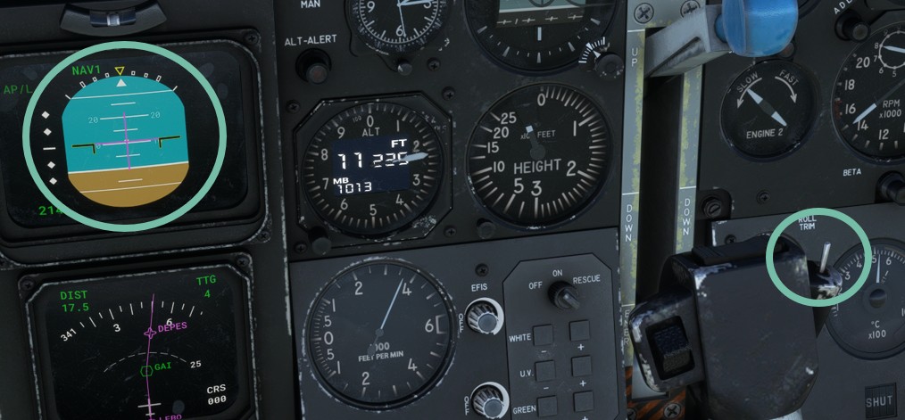
A target altitude can be set from the FMS or the EFB. Clicking on ALT button does not allow to go to a different altitude, but only to engage target altitude interception.
You need to use PITCH switch to select desired climb/descent rate. When the aircraft will arrive to target altitude, autopilot will automatically intercept and maintain it, with ALT light being on.
Here are the steps to follow to climb to a given altitude:
1. Enter target altitude (inside FMS or on the EFB tablet).
2. Engage autopilot that will automatically maintain current pitch.
3. Use flight director display to see pitch target value, that can be changed with PITCH switch.
4. ALT button will light up when target altitude is being intercepted.

5. ALT mode is now engaged and altitude is maintained.
Radio
Radio mode allows to intercept radials automatically based on NAV and TACAN frequencies, or to follow a GPS/FMS path.
Before enabling RADIO mode, please ensure that GPS/VLOC mode is set correctly with the following switch:
-
To “VLOC” if you want to follow a VOR/LOC/TACAN radial.
-
To “GPS” if you want to follow a GPS/FMS route.
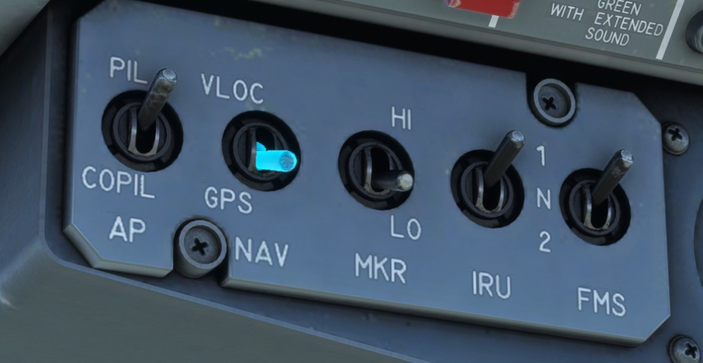
Then, ensure active source corresponds to the signal you want to follow (active source has a white border). In the following case, VOR2 radial will be tracked:
After clicking on RADIO button, active lateral and vertical modes will be displayed on top of the EADI as described here.
Radio mode is not magical and you will need to fly close to the track you wish to intercept before enabling the mode.
If current frequency is tuned to a VOR/TACAN station, autopilot will intercept currently selected radial and maintain it as long as a valid signal is received.
If an ILS frequency is tuned, autopilot will intercept both localizer (horizontal guidance) and glideslope (vertical guidance).
When a GPS unit is displayed (GNS 430 or GTN 650), Working Title systems are used to manage the autopilot. For this reason, GPS track from the GNS/GTN will be followed in radio mode instead of FMS flight plan (which can be different as GPS and FMS flight plans are not synchronized). That is why we advise not using GPS and FMS navigation at the same time.
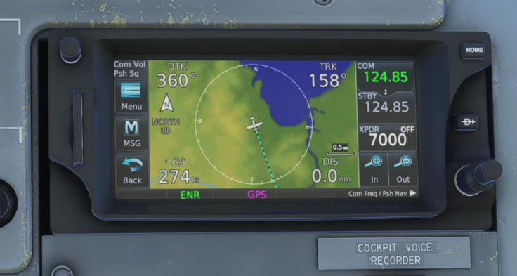
GPS
French Transall did not have any GPS display installed. However, we decided to add a GPS unit that you can display optionally from the EFB tablet.
It is based on the Working Title implementation which allows you to manage flight plans and navigate more easily.
It is connected to COM1/NAV1 frequencies.
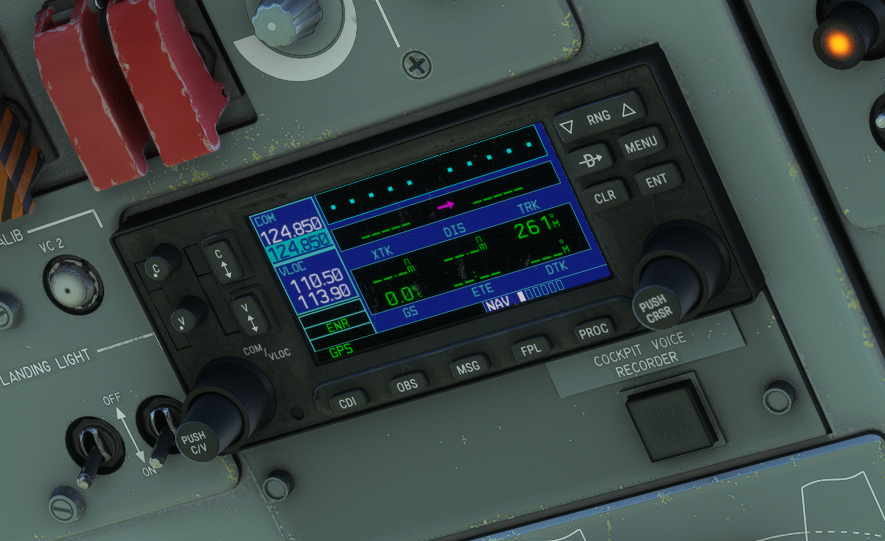
In MSFS 2024, you can also display a GTN 650 unit (PMS50 or TDS Sim Software).
As described in autopilot section, GPS route can be automatically followed by the autopilot in radio mode.
As GPS is using its own flight plan implementation, we strongly discourage to use it to manage flight plan at the same time as the FMS, as it could lead to wrong behaviours.
HUD
French Air Force C-160NG models were lately retrofitted with head up display (HUD).
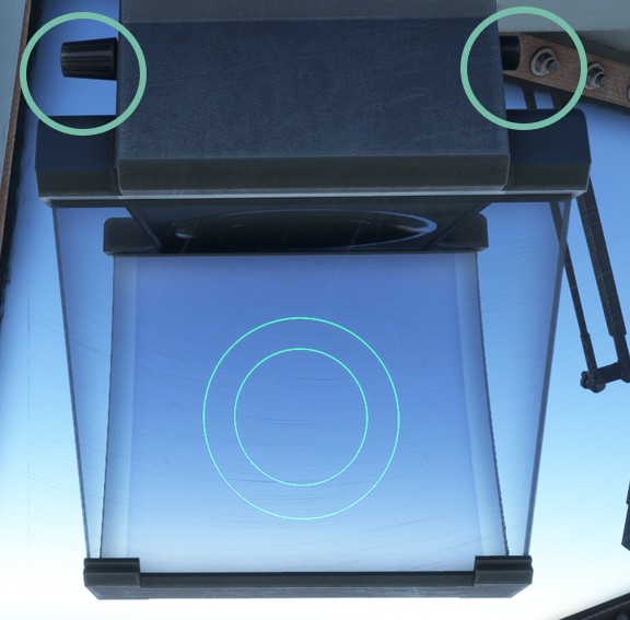
It can be displayed on both pilot and copilot seats, from the EFB tablet:
-
Left knob allows to turn the unit on and set the luminosity.
-
Right button makes the unit entering a test mode where two circles are displayed on the center, allowing to adjust seating position correctly.
With IRS aligned, the HUD will have the following layout:
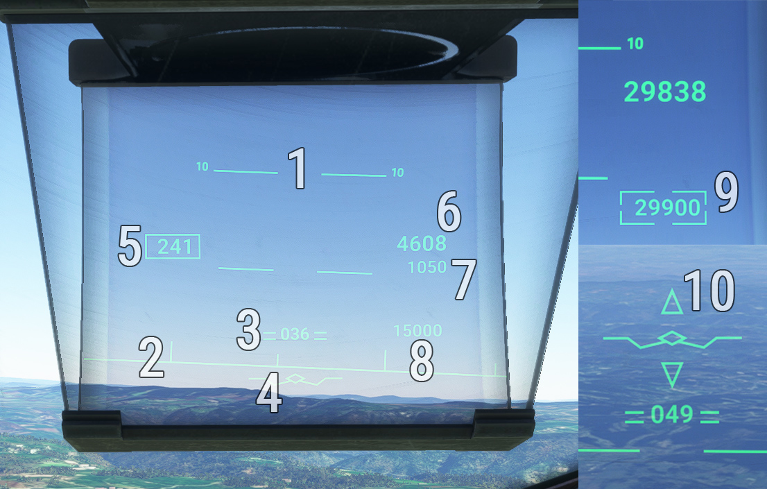
| # | Description | # | Description |
|---|---|---|---|
| 1 | Pitch graduations (for each 5°) | 6 | Altitude |
| 2 | Horizon line (vertical bar for each 5° heading) | 7 | Radio altitude (displayed below 2500 ft) |
| 3 | Pitch attitude indication with current heading | 8 | Target altitude |
| 4 | Flight path vector | 9 | Captured altitude frame |
| 5 | Airspeed | 10 | ILS glideslope indication (too high/too low) |
Flight path vector symbol varies with:
- Autopilot engaged.

- Landing gear down.

- Spoilers extended.

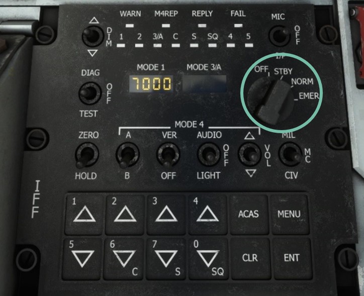
IFF / transponder
A complex military Identification Friend or Foe (IFF) is located on center console. For simulation purpose, only mode S (transponder) is implemented, as other military functionalities do not have any usage in the simulator.
Transponder mode (off/standby/on) is switched with the main knob, and current transponder code is changed with the bottom numeric keypad.
Weather radar
Weather radar enables to locate areas of bad weather during the flight, thanks to a visual indication of areas with high density of clouds. Radar antenna is positioned in aircraft radome (nose) and has a range of 200 nautical miles.
Visualization screen is located in the middle of front panel, and control panel on the bottom of center console.
Weather radar implementation in MSFS is very basic, hence several functionalities are inoperative.
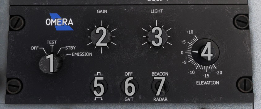
| # | Description | # | Description |
|---|---|---|---|
| 1 | Power knob (OFF, TEST, STBY, EMISSION) | 5 | Impulse length (inoperative) |
| 2 | Gain knob | 6 | Gain attenuation (inoperative) |
| 3 | Light knob (inoperative) | 7 | Radar/beacon mode (inoperative) |
| 4 | Elevation knob (inoperative) |
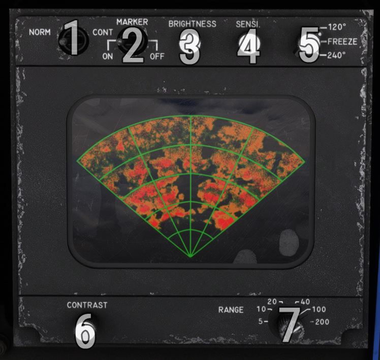
| # | Description | # | Description |
|---|---|---|---|
| 1 | Observation mode (inoperative) | 5 | Visualization (120°, 240°, freeze) |
| 2 | Markers display | 6 | Contrast knob |
| 3 | Brightness knob | 7 | Range knob |
| 4 | Sensibility knob (inoperative) |
BDHI
Bearing Distance Heading Indicator (BDHI) can be used in addition to the EHSI, for similar purpose.
Background rose is rotating to indicate current magnetic heading.
Depending on active radionavigation frequencies and switches position, a single needle and a double needle will indicate the direction of target station. A third needle is dedicated to TACAN station, and indicates an absolute bearing (angle relative to magnetic north) while other needles indicate a relative heading (angle relative to aircraft heading).
When one of the sources is not available, an orange flag is displayed.
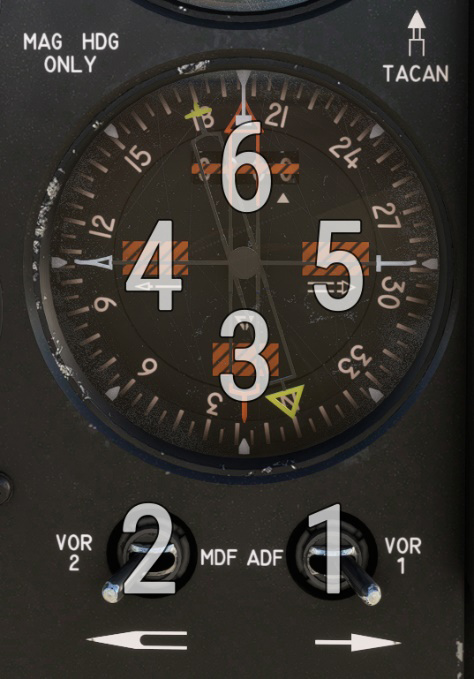
| # | Description | # | Description |
|---|---|---|---|
| 1 | Single needle source (ADF/VOR1) | 4 | Single needle source signal flag |
| 2 | Double needle source (VOR2/UHF) | 5 | Double needle source signal flag |
| 3 | TACAN signal flag | 6 | TACAN distance |
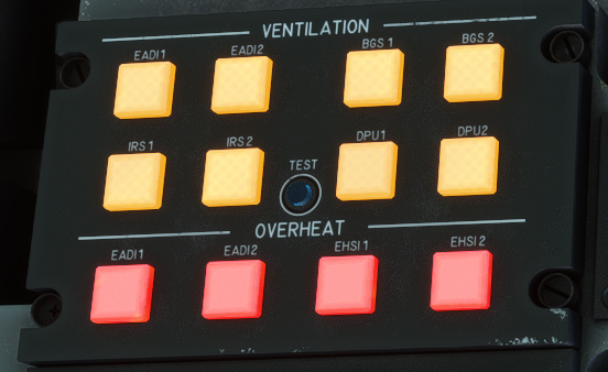
Ventilation
Ventilation is managed as soon as aircraft is powered.
Depending on systems powered, ventilators disposed in various places will be powered, and their current state is indicated on top console:
-
Electronic Attitude Director Indicator (EADI).
-
Electronic Horizontal Situation Indicator (EHSI).
-
Symbols generating box (BGS).
-
Inertial Reference System (IRS).
-
Display Processor Unit (DPU).
Last row is composed of red lights that will glow if one of the EADI or EHSI units are overheating.
A button allows to test all the lights of the panel.
Audio panel
Each crew member has an audio panel to manage sound related to communication and radiocommunication.
Knobs allow to set volume for each audio input: COM, VOR, marker, TACAN, ADF, etc.
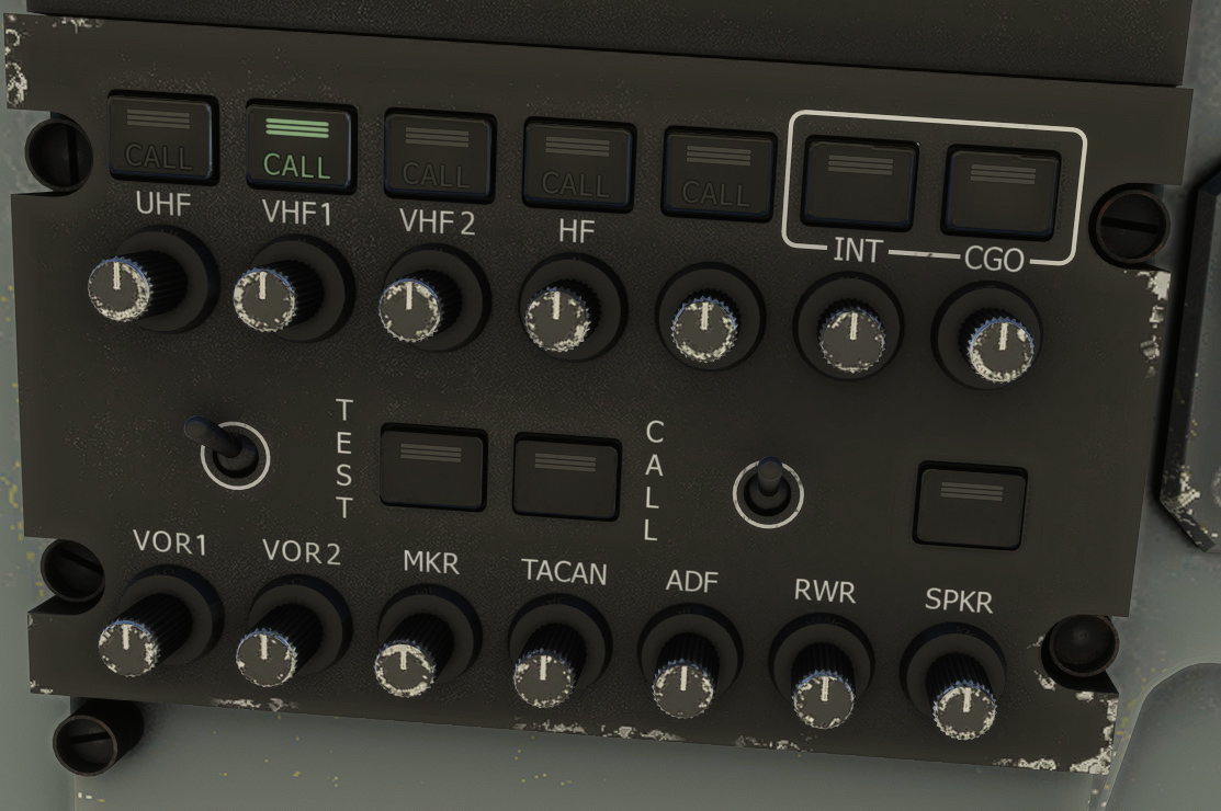
As there is a single sound output in the simulator, those three panels will result to the same changes to sound variables.