Engines and auxiliary power
Engines
Description
The aircraft is powered by two Rolls Royce “Tyne 22” turboprop engines, providing maximum 5,665 HP (ISA conditions) with 510 kilograms of residual thrust.
This turboprop is twin-spool with:
-
Axial compressor with six-stage LP and nine-stage HP.
-
Turbine with three-stage LP and single-stage HP.
Each engine is connected to:
-
Two electrical generators.
-
Two hydraulic pumps.
-
An accessory drive for accessories and bleed air generation.
Controls
Main engine controls are located in the central console.
In the real aircraft, more settings are available (for example separate “on ground” and “in flight” zones for the power lever) but were simplified for usability purpose within the simulator.
Condition levers
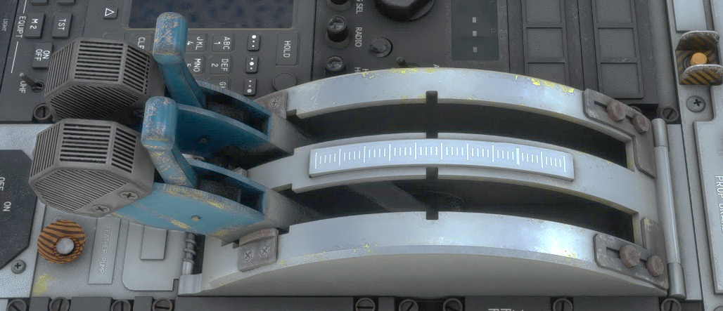
Condition levers control fuel mixture with three distinct zones:
-
Lower position: fuel cut-off.
-
Middle position: low idle (minimum fuel mixture).
-
High position: high idle (maximum fuel mixture).
The embedded Fuel Control Unit (FCU) can manage auto-mixture depending on aircraft speed, altitude and requested power (from power levers).
Condition levers can be bound to physical controllers using the following bindings:
- Condition lever cutoff/low idle/high idle to switch between the three lever positions.
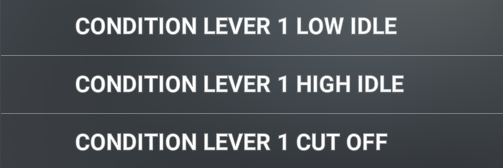
- Mixture axis to set lever more precisely between middle and high positions.

Power levers
Power levers control both FCU and Propeller Control Unit (PCU) and have two zones:
-
From 20° to 70°: Proportional forward thrust request.
-
From 20° to 0°: Proportional reverse thrust request.
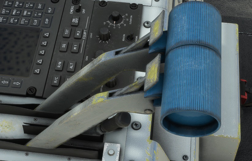
Idle levers
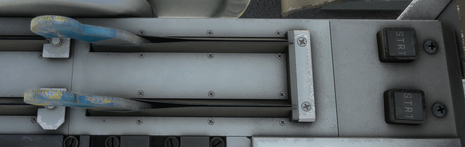
Idle lever purpose is to control fuel injection during engine startup. They have two positions:
-
A start position (“STRT”) controlling the “start idle” valve for the engine to reach appropriate N1 RPM.
-
A normal position (“NORM”) once engine is started.
A dedicated magnetic indicator is located above each lever to see its current position.
Methanol
Take-off performance of the “Tyne” engine decreases from 1% per degrees above I.S.A conditions. A water-methanol circuit can be enabled during takeoff to ensure maximum performance.
Methanol injection system has been simulated but will not bring any performance increase as the simulator does not allow to implement this specific behavior. It is only available for immersion and roleplay purposes.
Methanol is injected in first stage of low-pressure compressor, thus decreasing air temperature and allowing to inject more fuel.
Two pumps allow a flow of 2225 liters per hour at 1.5 bars. Total capacity is 325 liters, allowing around 10 minutes of injection.
On top console:
-
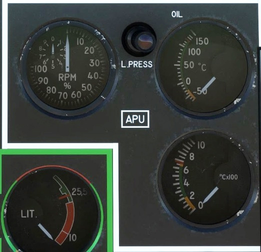
One gauge with total methanol level.
-
Two switches to turn on pumps.
-
One light per pump to show its operation.
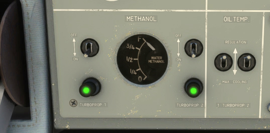
Once pumps are running, injection will start only if condition levers are fully forward and if engine torque is above 75 PSI.
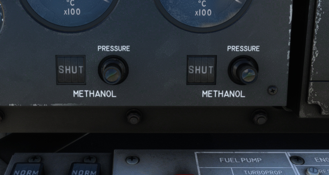
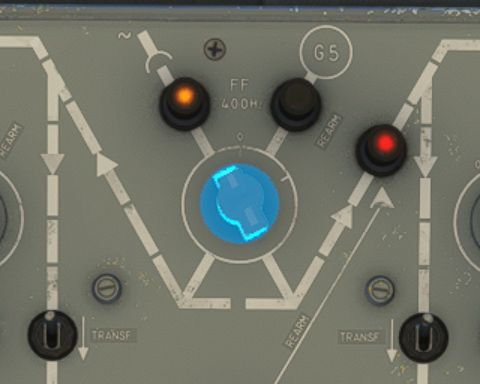
On front panel:
-
One light per engine lighting up when methanol injection pressure is above 0.62 bars.
-
One magnetic indicator per engine showing “OPEN” once injection valve is opened.
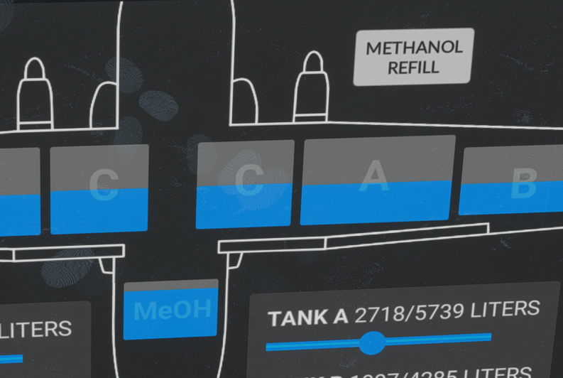
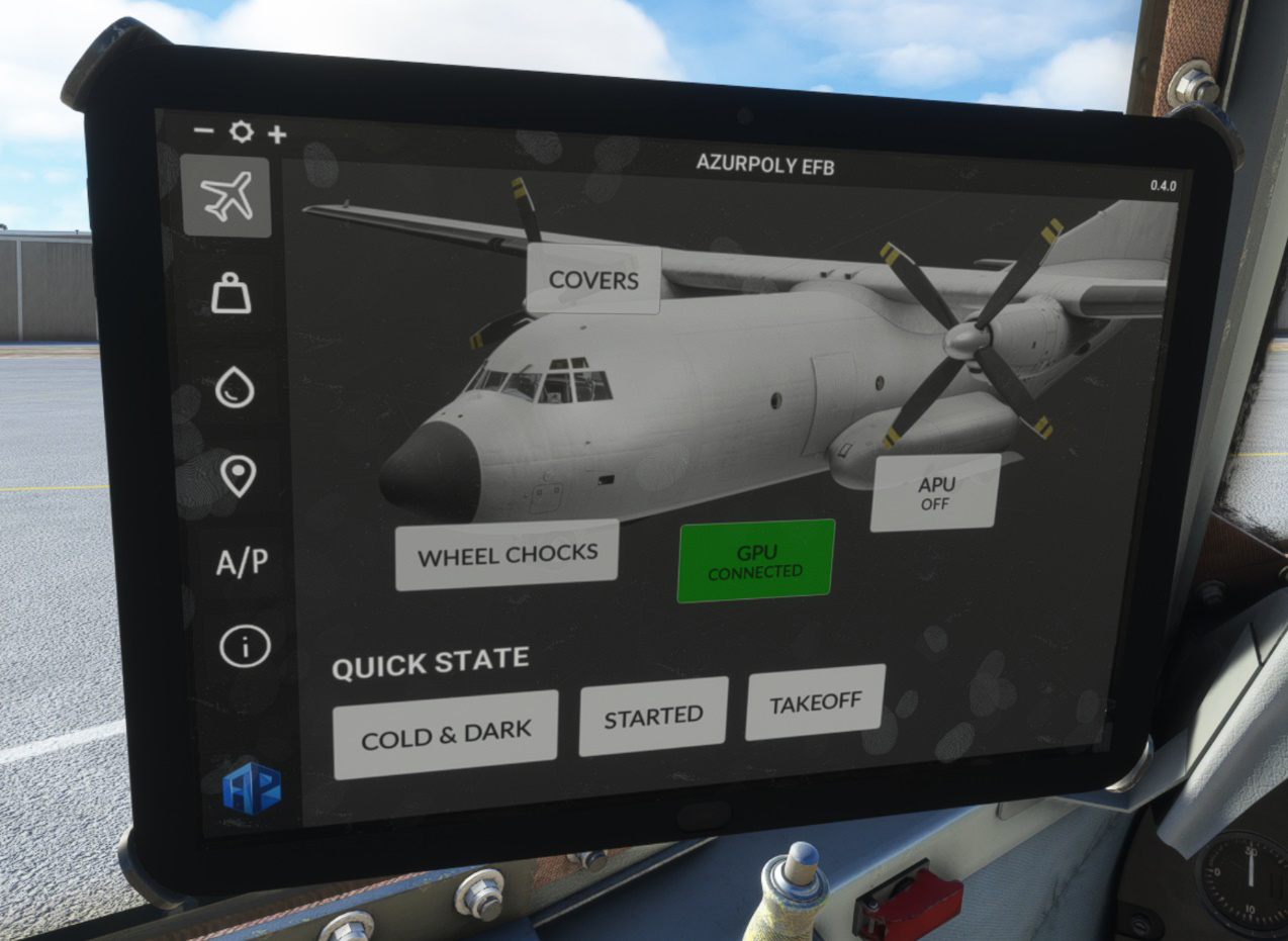
Methanol level is also displayed on the EFB, with a button to refill:
Auxiliary power
Turbo generator group
Turbo generator group is located in front of left landing gear. It is slightly different as a typical APU (auxiliary power unit) as it does not only generate electricity and bleed air, but also hydraulic power (on the red hydraulic circuit). It is composed of a AirResearch turbine, rated 200 HP.
The connected generator is G5, rated 60 kVA, allowing electrical supply when both engines are off. Bleed air for engine start and air conditioning is generated with a flow of 0.905 kilograms per second.
APU is self-regulated and does not need any manual action when running. It can be monitored through its dedicated front panel section with:
-
%RPM gauge.
-
Oil temperature gauge.
-
Exhaust gas temperature gauge.
-
Low oil pressure light when pressure is below 0.1 bars.
APU commands are gathered on center console:
-
Air inlet switch.
-
Starter switch.
-
Bleed air switch.
-
Flight startup switch.

Air inlet needs to be opened prior to starting the APU as it allows air supply. Starter switch will trigger an automatic sequence after which APU will reach and maintain 100% RPM.
Closing air inlet will automatically shut the APU down.
GPU
A ground power unit can be connected to the Transall to provide direct current, when the battery is on but not being recharged by the APU generator.
The real aircraft can also be supplied with alternating current, but both are managed with the same unit within the simulator. See electrical section for more information.
Power unit can be connected via the EFB:
Transfer to main electrical source is done from upper console:
Propeller
Description
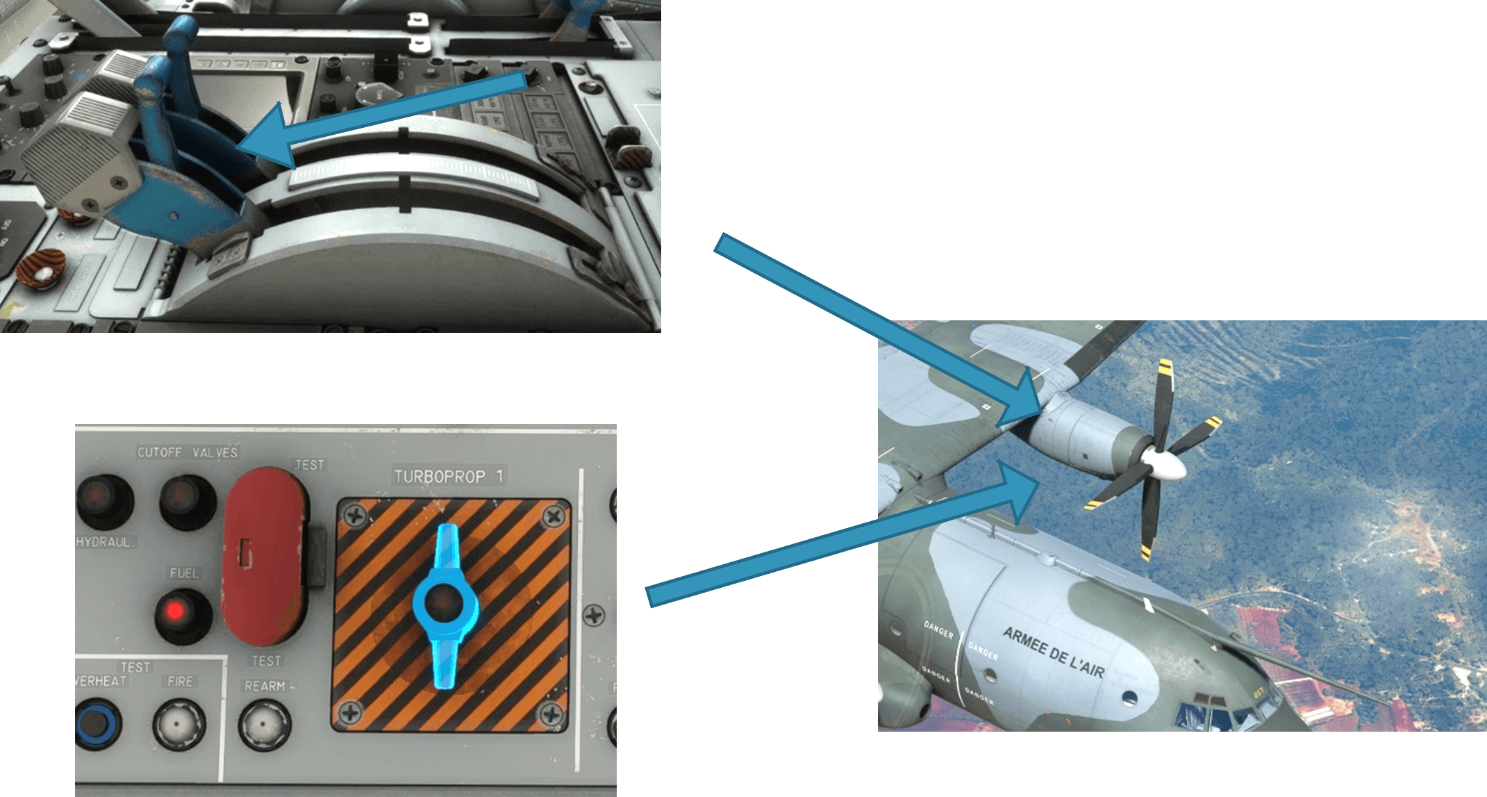
Each engine is equipped with a four-bladed constant speed propeller, with a diameter of 5.486 m. The model on the later versions of the Transall is “Ratier Figeac FH152-2”, built with composite materials instead of metal on previous versions.
Each blade covers an angle of 100° from minimum to maximum pitch, allowing a “reverse” mode to land on small distances. Engine lubricant is used as hydraulic fluid for propeller pitch changes, with a safety edge in case of oil pressure drop.
Controls
Propeller is controlled automatically depending on power lever input. To cover engine power loss scenarios in flight and avoid excessive drag, it will be feathered in two cases:
-
Condition lever in cut-off position.
-
Fire shut-off valve closed (upper console).
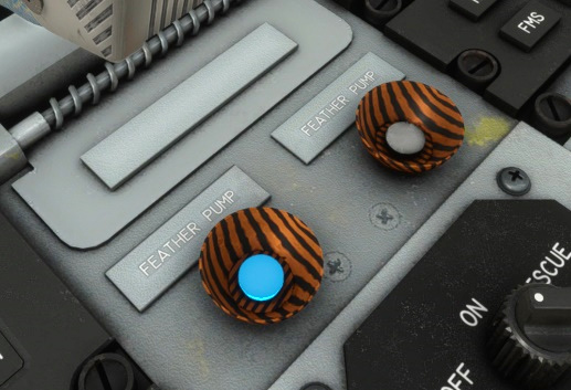
While on-ground with engines off, an electrical motor can be used to put propeller in feather position:
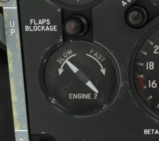
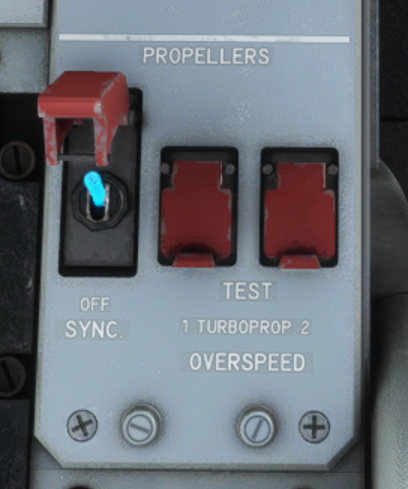
Synchronization
Right engine propeller speed can be synchronized with left engine propeller to decrease noise and vibrations while in cruise.
System is enabled with a switch on the center console, and will work as soon as speed difference is not too important (below 150 RPM).
A synchroscope allows to see rotation speed differences between two engines. Right engine propeller rotates faster than left engine propeller if the needle rotates clockwise, and slower if counterclockwise.