Electrical
Description
Electrical installation consists of:
-
Two independent three-phase circuits (115V and variable frequency 380~580Hz), named XP1 and XP2, each powered by a 60kVA generator (named G1 & G2).
-
Two independent three-phase circuits (115V and fixed frequency 400Hz), named XP3 and XP4, each powered by a 9kVA generator (named G3 & G4).
-
One 28V DC (direct current) circuit, named PP2, and powered by G1 and G2 generators, via two 6kW transformer-rectifiers (named TR1 and TR2). Two 40Ah batteries are connected to this circuit. As described in GPU, a ground power unit can also be used to supply this circuit.
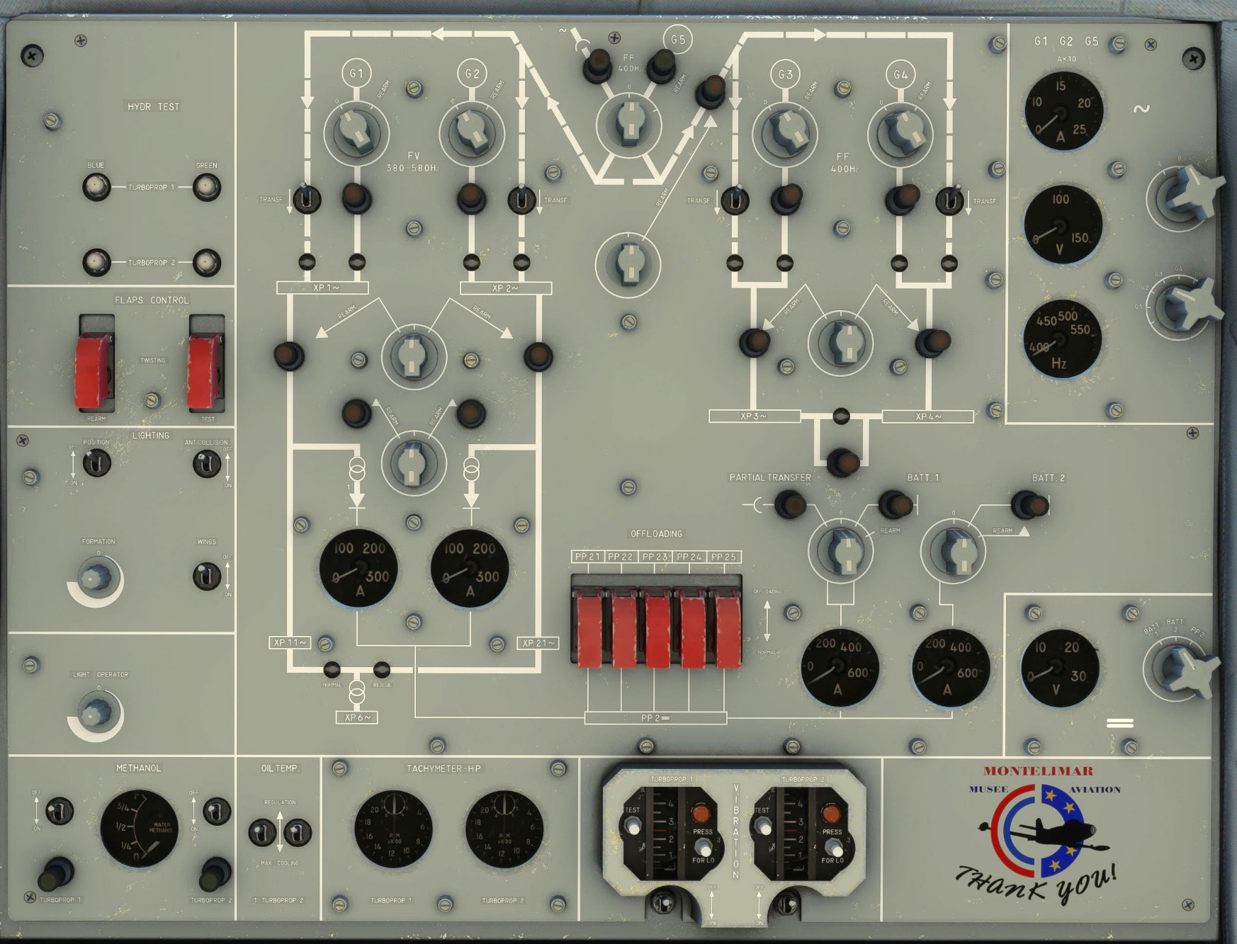
Everything related to electrical network is managed from the top part of the upper panel, including:
-
Batteries switches.
-
Generators switches.
-
Visualization of intensity, voltage and frequency for each generator.
-
Visualization of intensity and voltage for batteries and transformer-rectifiers.
Batteries
Two batteries provide electrical power while engines are stopped. They have a limited capacity of 40Ah each and can power basic elements such as APU starter, ventilation, interior lighting, etc.
They can bet connected or disconnected from the DC network using their dedicated selector.
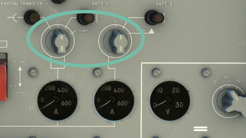
They can be monitored thanks to:
-
A load gauge graduated from 50A to 600A.
-
A voltage gauge graduated from 0V to 30V.
Nominal voltage is 25.5V. A red light indicates a low capacity for the battery.
Generators
Each engine ships a 60kVA generator (G1 for left engine, G2 for right engine) and a 9kVA generator (G3 for left engine, G4 for right engine), to guarantee redundancy.
A fifth generator named G5, connected to the APU, can power each three-phase circuit.
They all can be connected or disconnected from their network using the dedicated knob.
They can be monitored independently using gauges on the right side of the panel.
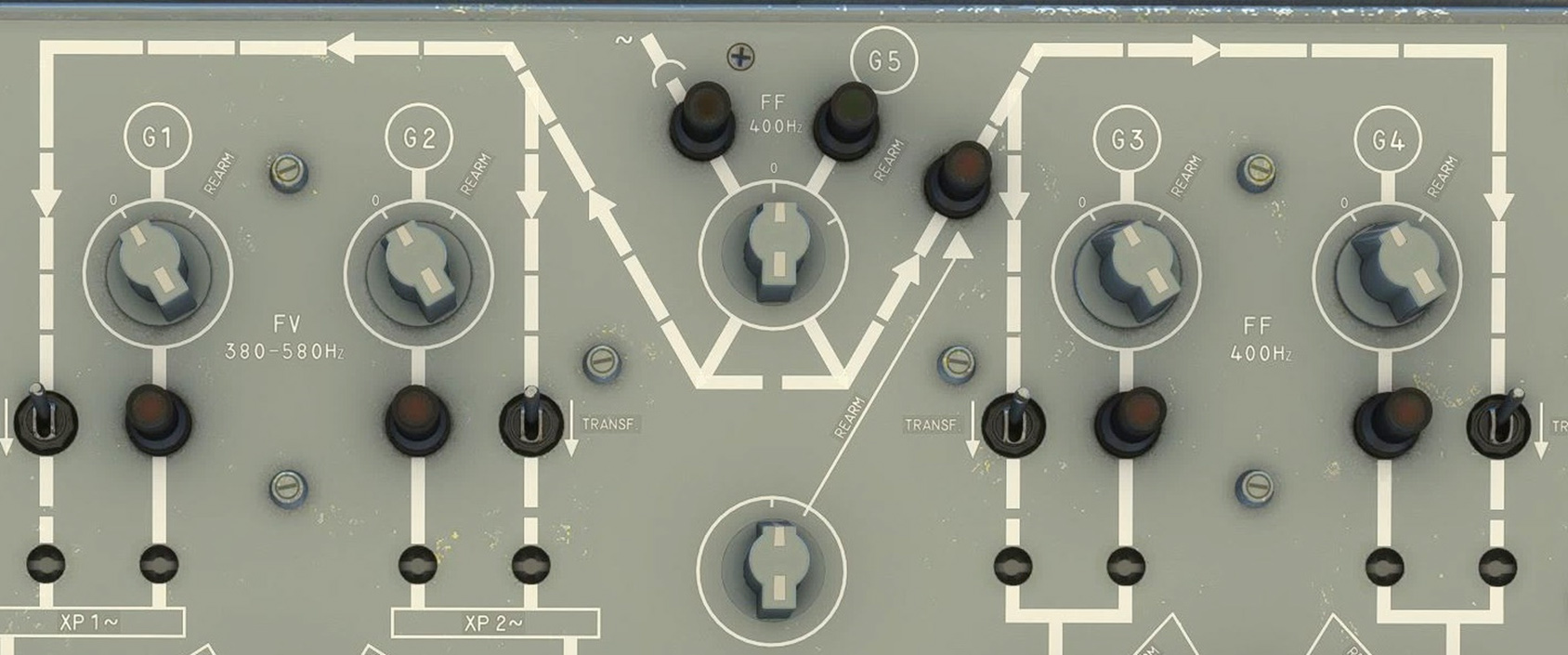
When APU nominal RPM value is reached, G5 generator is available. In this case it can be selected using GPU/G5 selector knob. A green light turns on when G5 is selected.
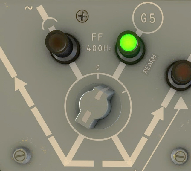
On each generator circuit, a red light indicates either a failure or a loss of power.
When all four engine generators are off and only APU (or GPU) is running, transfer switches must be set to ON (switch forward). They insure connection between APU/GPU circuit and other generators circuits.
In normal conditions, no red light should be on.
Lights
Exterior
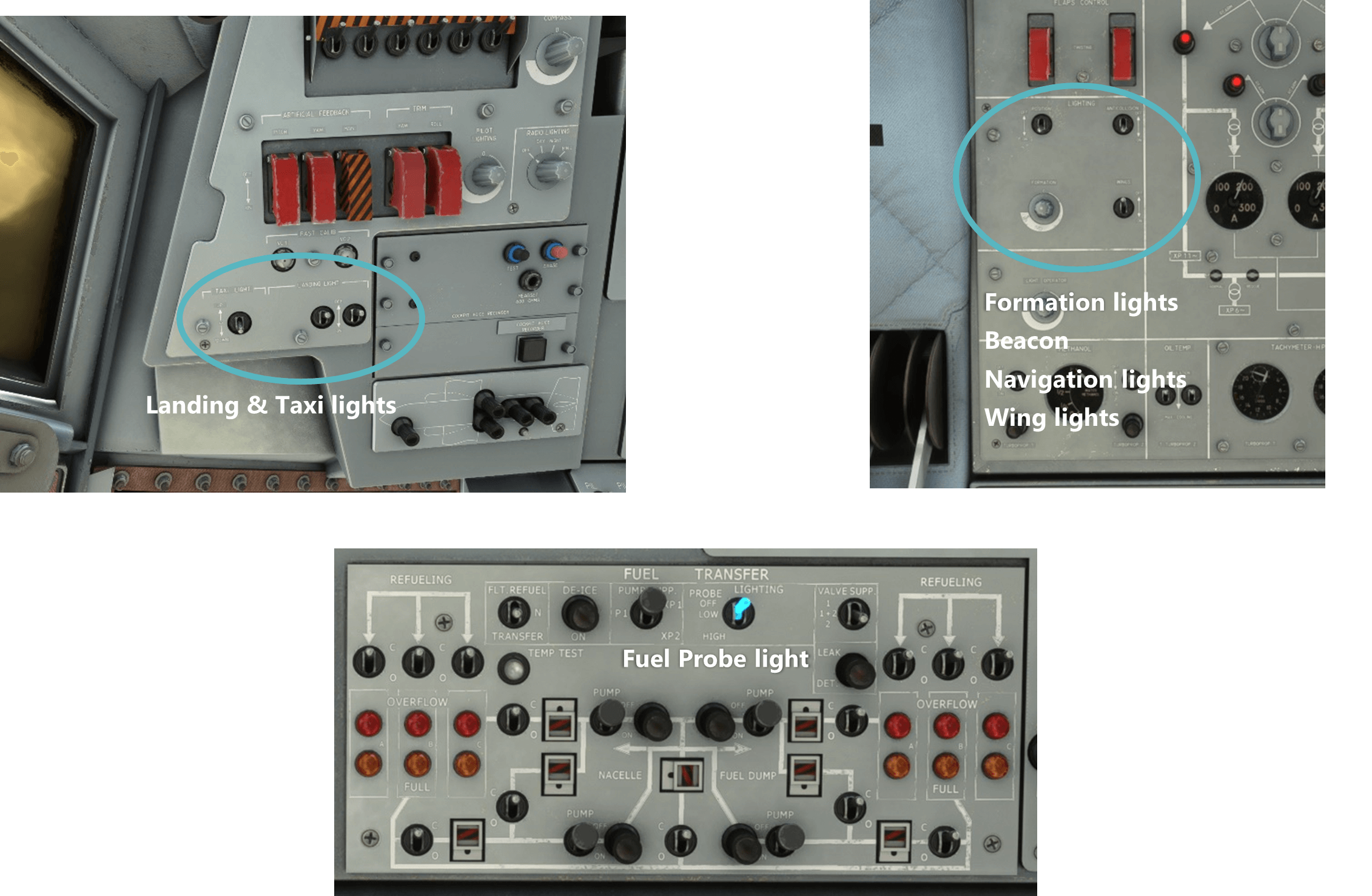
All exterior lights are managed on top console:
-
Taxi lights.
-
Landing lights (x2).
-
Position / navigation lights.
-
Anticollision (beacon).
-
Formation lights.
-
Wing lights.
-
Refueling probe light.
Interior
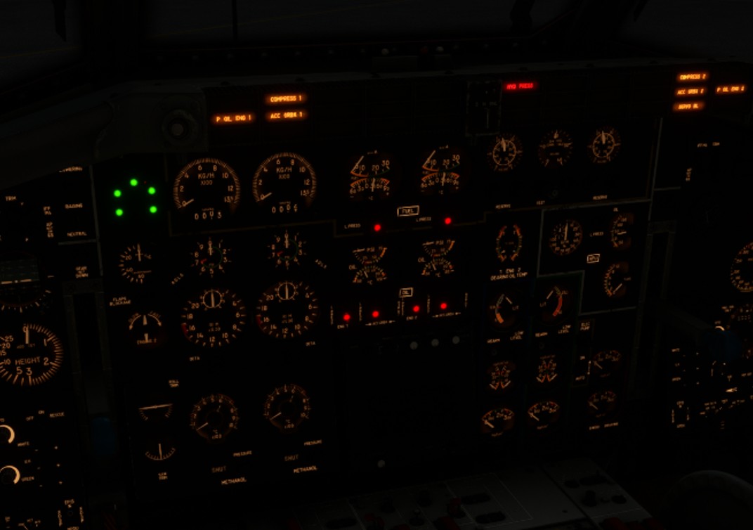
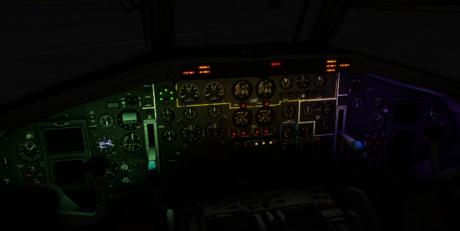
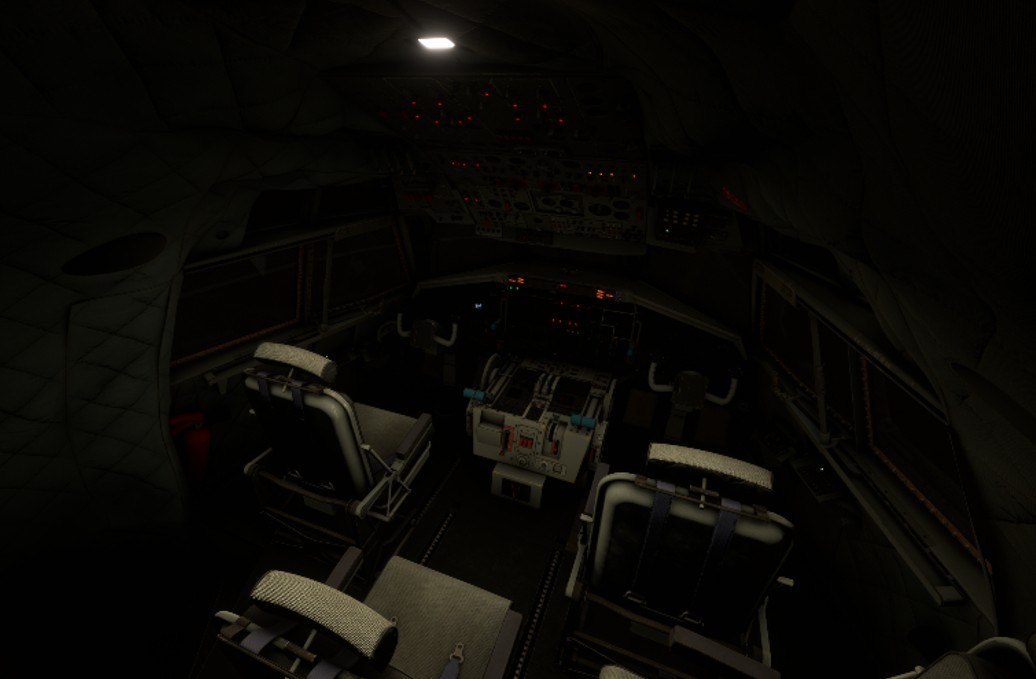
A lot of interior lights are available in the Transall. You will find knobs and switches for interior lights in several places of the cockpit. Some lights have been enhanced compared to the real aircraft (e.g. backlighting) to ensure a good readability of all the instruments by night.
The interior lighting is composed of:
-
One lamp for each cabin crew (pilot, copilot, engineer, navigator).
-
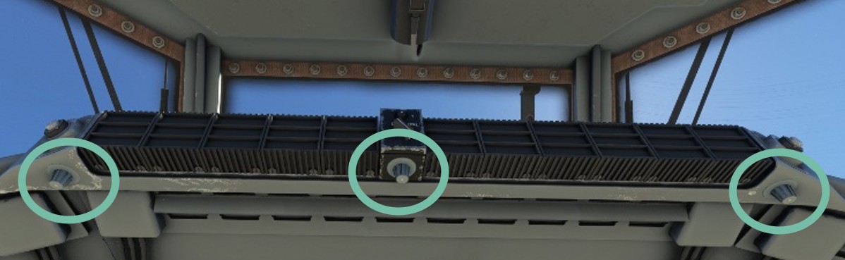
Three neon lights on the front panel.
-
Panel backlighting.
-
A dome light.
-
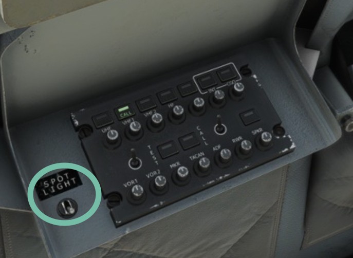
Two spotlights on the sides.
-
Magnetic compass light.
For each panel, backlighting intensity can be set with a knob.
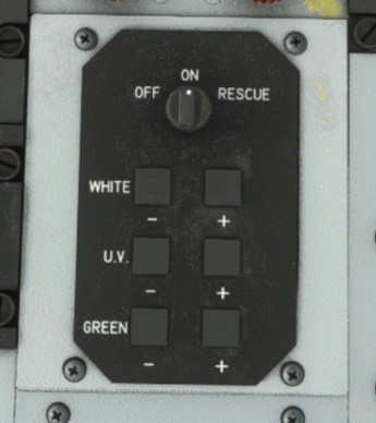
You will also find command panels for neon lights. Each panel allows to choose intensity of white, green and UV neon in their associated zone.
On ground or when crusing, cabin can be illuminated by two sides spotlights.
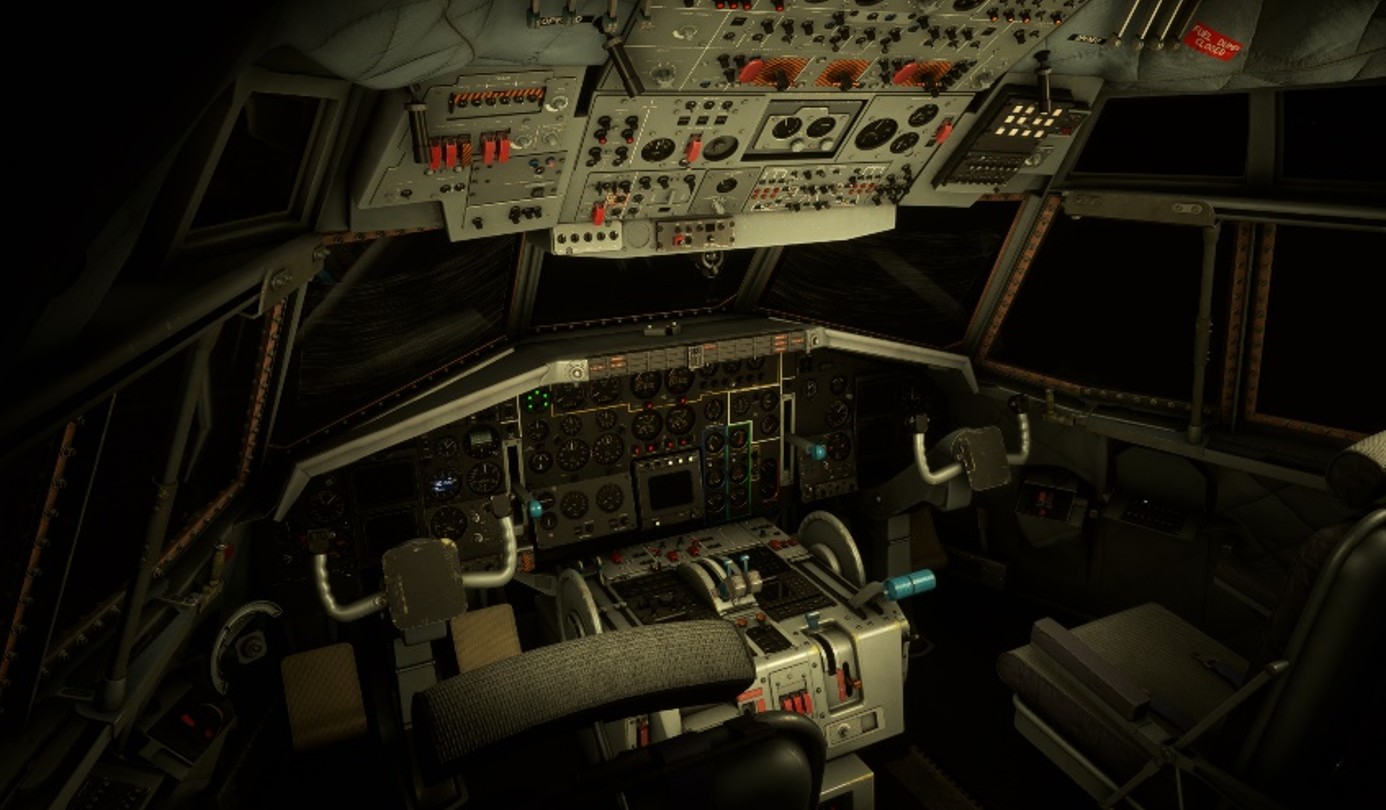
There is another lower intensity dome light on cabin ceiling that can be switched by clicking on it.
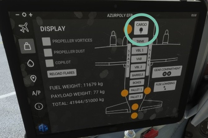
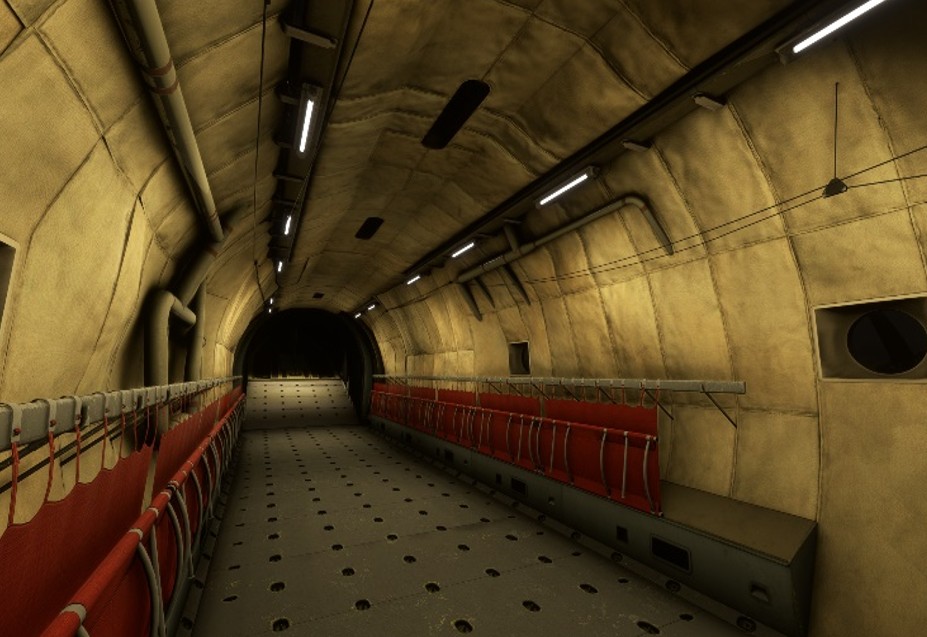
Cargo bay can be illuminated as well from the tablet (EFB).
Alarms
All alarms are gathered in a long panel shared between pilot and copilot, on top of front panel.
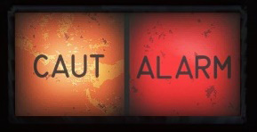
Two severity levels are considered:
-
CAUTION, orange color.
-
WARNING, red color.
Each time an alarm is raised by the system, main caution or warn light will be illuminated and the corresponding alarm will be displayed in the grid.
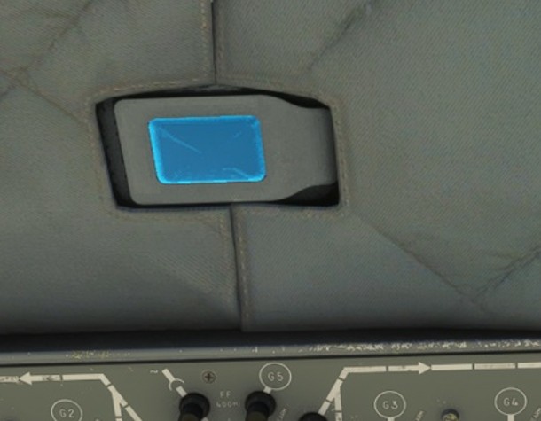
Each red alarm will generate a continuous beep tone that can be stopped by pressing the pad.
| ENG DFR 1 | COMPRESS 1 | GENERATOR 1 | ARTHUR YAW | APU FIRE |
| Engine 1 defrost failure | Engine 1 compressor oil overheat (> 120 °C) or low pressure (< 3.35 bars) | Generator 1 failure | Artificial feedback failure (yaw) | APU fire |
| P OIL ENG 1 | ACC GRBX 1 | GENERATOR 3 | ARTHUR PITCH | OVRHT ENG 1 |
| Engine 1 low oil pressure (< 2.06 bars) | Engine 1 gearbox oil overheat (> 120 °C) or low pressure (< 3.35 bars) | Generator 3 failure | Artificial feedback failure (pitch) | Engine 1 overheat (breather circuit > 180 °C) |
| VIBRATIONS | GENERATOR 5 | T R U | AUTO PILOT | FIRE ENG 1 |
| High engine vibrations (>2.5) | Generator 5 failure | Transformer-rectifier unit failure | Autopilot disconnection | Engine 1 fire |
| HYD PRESS | HYD RES | CYCLERS | GENERATOR 2 | COMPRESS 2 | ENG DFR 2 |
| Blue/green hydraulic low pressure (< 122.6 bars) | Blue/green hydraulic reservoir low level | Heating cyclers failure | Generator 2 failure | Engine 2 compressor oil overheat (> 120 °C) or low pressure (< 3.35 bars) | Engine 2 defrost failure |
| OVRHT ENG 2 | CABIN ALT | WINGS DE-ICE | GENERATOR 4 | ACC GRBX 2 | P OIL ENG 2 |
| Engine 2 overheat (breather circuit > 180 °C) | Loss of cabin pressure Cabin alt > 11700ft | Wings de-ice failure | Generator 4 failure | Engine 2 gearbox oil overheat (> 120 °C) or low pressure (< 3.35 bars) | Engine 2 low oil pressure (< 2.06 bars) |
| FIRE ENG 2 | DIFF ALT | TAIL DE-ICE | BATTERIES | SERVO BL | VENTILATION |
| Engine 2 fire | High differential pressure (> 335 gr/cm²) | Tail de-ice failure | Battery disconnection | Commands blocking authorization if blue pressure < 80 bars | Ventilation failure |
De-icing
Complex de-icing systems are operated to fly in icing conditions.
De-icing installation ensures the protection of:
-
Airframe (wings and tail).
-
Engines and APU.
-
Pitot tubes and AOA probe.
-
Windshield.
-
Servo commands.
Those systems are all controlled from the upper console.
Probes and sensors
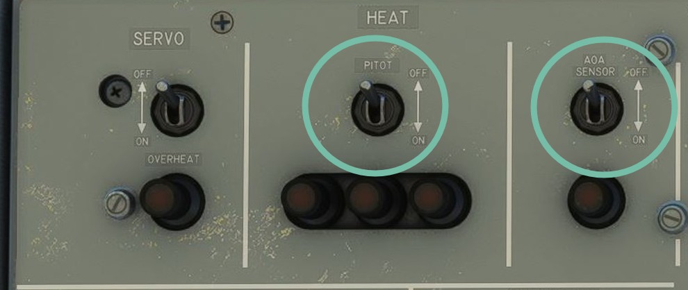
During any flight, pitot tubes and angle of attack sensor heating should be functioning.
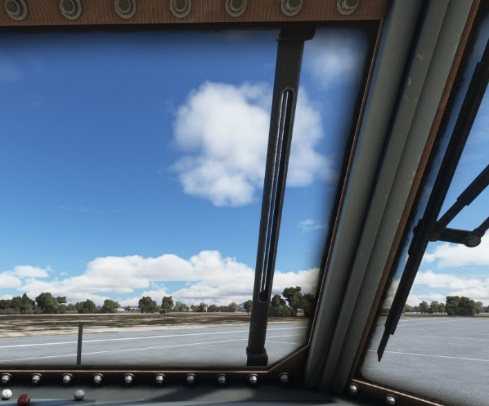
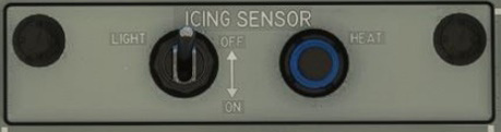
To assess icing intensity while flying in icing conditions, a luminous tube is located in front of the windshield.
It can normally be heated up in order for the crew to visualize the speed of ice formation on it. This functionality is not simulated for now because of technical limitations. However, the tube can be lighted from the de-icing panel.
Windshield
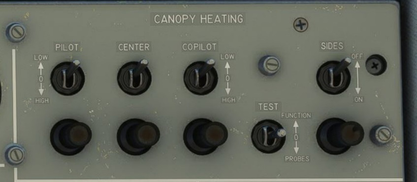
Windshield heating is divided in four zones (pilot, center, copilot and sides). Two heat intensities can be set depending on the severity of icing conditions.
Each zone has a light which is on when heating is not functioning.
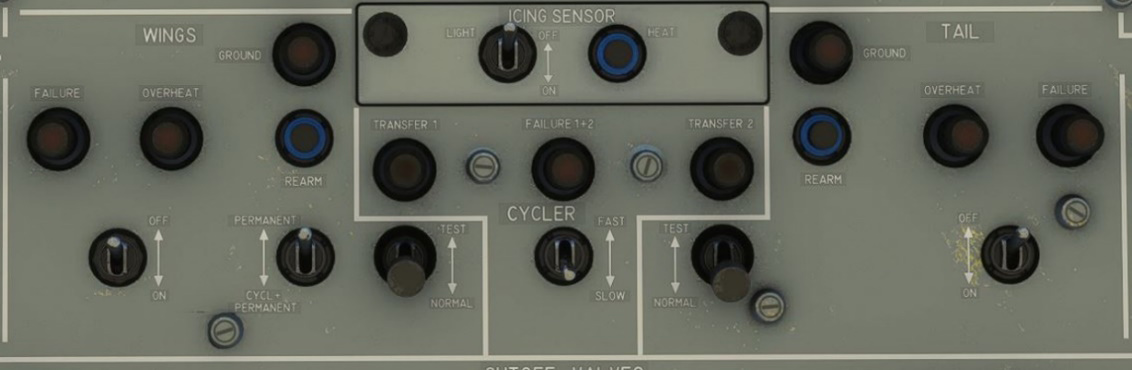
Airframe
Both wings and tail share the same de-icing technology located on the leading edges, with several zones being electrically heated.
Two types of heating are available: permanent heating (continuous) and cycled heating. A switch allows to switch between those different modes.
Heating circuits are protected and monitored. For both wings and tail de-icing, red lights indicate:
-
System failure.
-
Overheat.
-
Active de-icing while aircraft is on ground (which should be avoided).
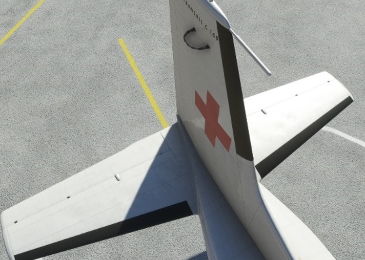
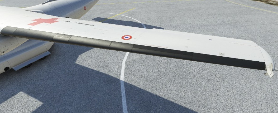
Heated zones are very distinctive in the exterior model as they are made of black nitrile for corrosion protection:
Engines & APU
Engines and APU de-icing is achieved by three different manners:
-
Electrical heating.
-
Hot air.
-
Hot oil.
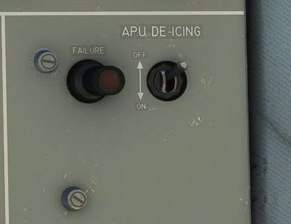
APU air inlet periphery is electrically heated, and hot air is extracted from the APU compressor to heat the air inlet zone as well.
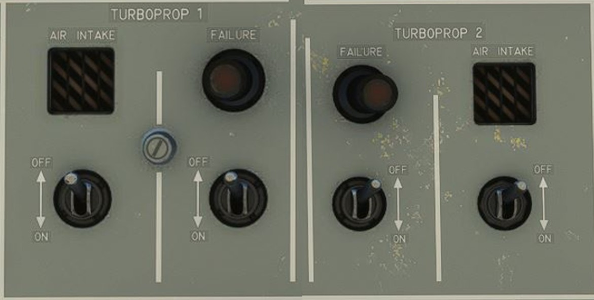
Regarding engines:
-
Air intake crown is electrically heated.
-
Hot air extracted from high pressure compressor is released on first stage of compressor blades, around air intake and oil radiator entry.
-
Engine oil is circulating around air intake, effective once the engine is running.
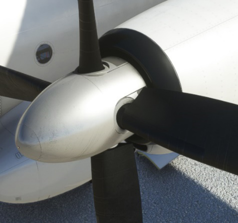
Propeller de-icing works the same way as airframe de-icing but only with cycled heating.
Propeller cone and blade root only are heated.
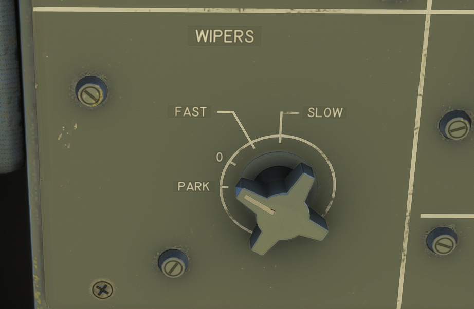
Wipers
Two wipers (pilot and copilot side) are used to evacuate rain on the windshield.
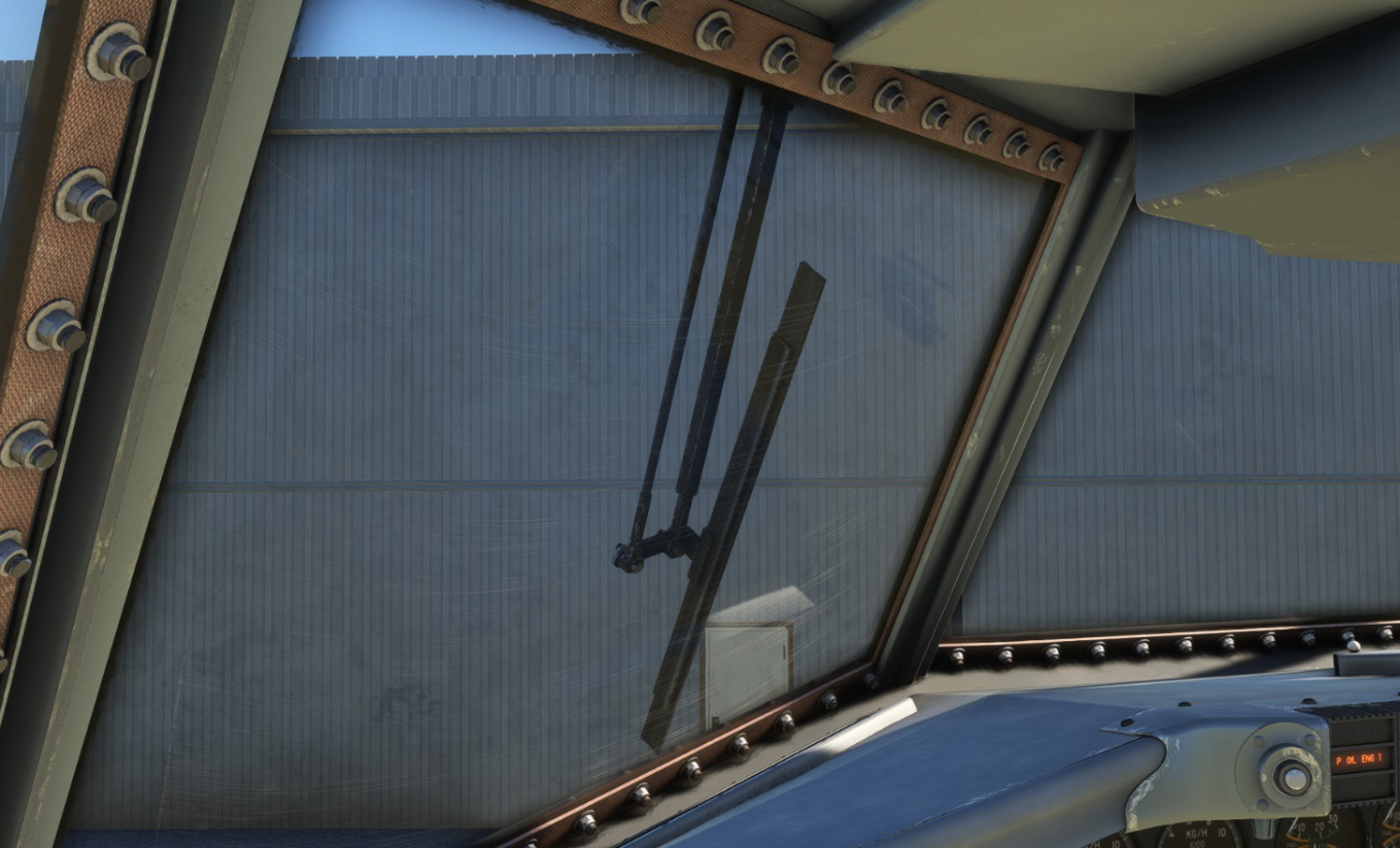
A knob on each side of upper console controls wipers:
-
SLOW and FAST positions to turn the wiper on with two possible speeds.
-
0 position to stop the wiper.
-
PARK position is unstable and will let the wiper go to his initial position, before being switched off.