Performance
Speed tables
To keep a safety margin at any moment of the flight with stall speed (VS), a specific speed called “reference speed” (VREF) must be respected at any time. VREF depends on three factors:
-
Aircraft weight.
-
Flaps angle.
-
Load factor.
As those factors are all changing continuously, the following simple calculation is used for reference speed:
where VSα30° is the stall speed with flaps 30° and landing gear down.
Here is the table specifying normal operating speeds for any weight:
-
Takeoff speeds (V2 and VR) with flaps 10° and 20°.
-
Approach speed (VAPP) with different flaps settings (VREF corresponds to flaps 30°).
-
Stall speed (VS) with each flaps setting.
| TAKEOFF | LANDING | STALL | |||||||||||
|---|---|---|---|---|---|---|---|---|---|---|---|---|---|
| α10° | α20° | α0° | α20° | α30° | α40° | α0° | α10° | α20° | α30° | α40° | |||
| Weight (tons) | VR | V2 | VR | V2 | VAPP | VS | |||||||
| 30 | 96 | 98 | 89 | 92 | 111 | 95 | 91 | 88 | 85 | 78 | 73 | 70 | 67 |
| 31 | 97 | 100 | 91 | 93 | 112 | 97 | 92 | 89 | 87 | 80 | 74 | 71 | 68 |
| 32 | 99 | 101 | 92 | 95 | 115 | 98 | 94 | 91 | 88 | 81 | 76 | 72 | 69 |
| 33 | 100 | 103 | 94 | 96 | 116 | 100 | 95 | 92 | 90 | 82 | 77 | 73 | 70 |
| 34 | 102 | 104 | 95 | 97 | 118 | 101 | 97 | 94 | 91 | 83 | 78 | 74 | 72 |
| 35 | 103 | 106 | 96 | 99 | 120 | 103 | 98 | 95 | 92 | 85 | 79 | 75 | 73 |
| 36 | 105 | 107 | 98 | 100 | 122 | 104 | 100 | 96 | 94 | 86 | 80 | 76 | 74 |
| 37 | 106 | 109 | 99 | 101 | 124 | 106 | 101 | 98 | 95 | 87 | 81 | 78 | 75 |
| 38 | 108 | 110 | 100 | 103 | 125 | 107 | 102 | 99 | 96 | 88 | 82 | 79 | 76 |
| 39 | 109 | 112 | 102 | 104 | 127 | 108 | 104 | 100 | 98 | 89 | 83 | 80 | 77 |
| 40 | 110 | 113 | 103 | 105 | 129 | 110 | 105 | 102 | 99 | 91 | 84 | 81 | 78 |
| 41 | 112 | 115 | 104 | 107 | 130 | 111 | 106 | 103 | 100 | 92 | 86 | 82 | 79 |
| 42 | 113 | 116 | 105 | 108 | 132 | 113 | 107 | 104 | 101 | 93 | 87 | 83 | 80 |
| 43 | 115 | 117 | 107 | 109 | 133 | 114 | 109 | 105 | 102 | 94 | 88 | 84 | 81 |
| 44 | 116 | 119 | 108 | 111 | 135 | 115 | 110 | 107 | 104 | 95 | 89 | 85 | 81 |
| 45 | 117 | 120 | 109 | 112 | 136 | 117 | 111 | 108 | 105 | 96 | 90 | 86 | 82 |
| 46 | 118 | 121 | 110 | 113 | 137 | 118 | 113 | 109 | 106 | 97 | 91 | 86 | 83 |
| 47 | 120 | 123 | 112 | 114 | 139 | 119 | 114 | 110 | 107 | 98 | 92 | 87 | 84 |
| 48 | 121 | 124 | 113 | 115 | 140 | 120 | 115 | 108 | 99 | 92 | 88 | ||
| 49 | 122 | 125 | 114 | 117 | 142 | 122 | 116 | 109 | 100 | 93 | 89 | ||
| 50 | 126 | 118 | 143 | 123 | 117 | 110 | 101 | 94 | 90 | ||||
| 51 | 127 | 119 | 144 | 124 | 118 | 111 | 102 | 95 | 91 | ||||
Related notes:
-
When approaching with 40% spoilers, you should increase VAPP by 5 knots.
-
Takeoff with a weight above 49.150 tons is allowed only with 0° flaps.
-
Stall speed increases with load factor (and hence roll angle): 8% for 30°, 19% for 45°, 40% for 60°.
Takeoff
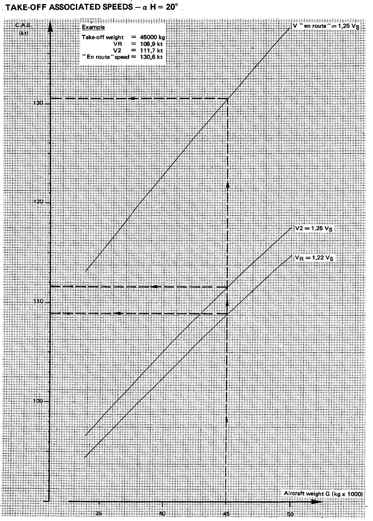
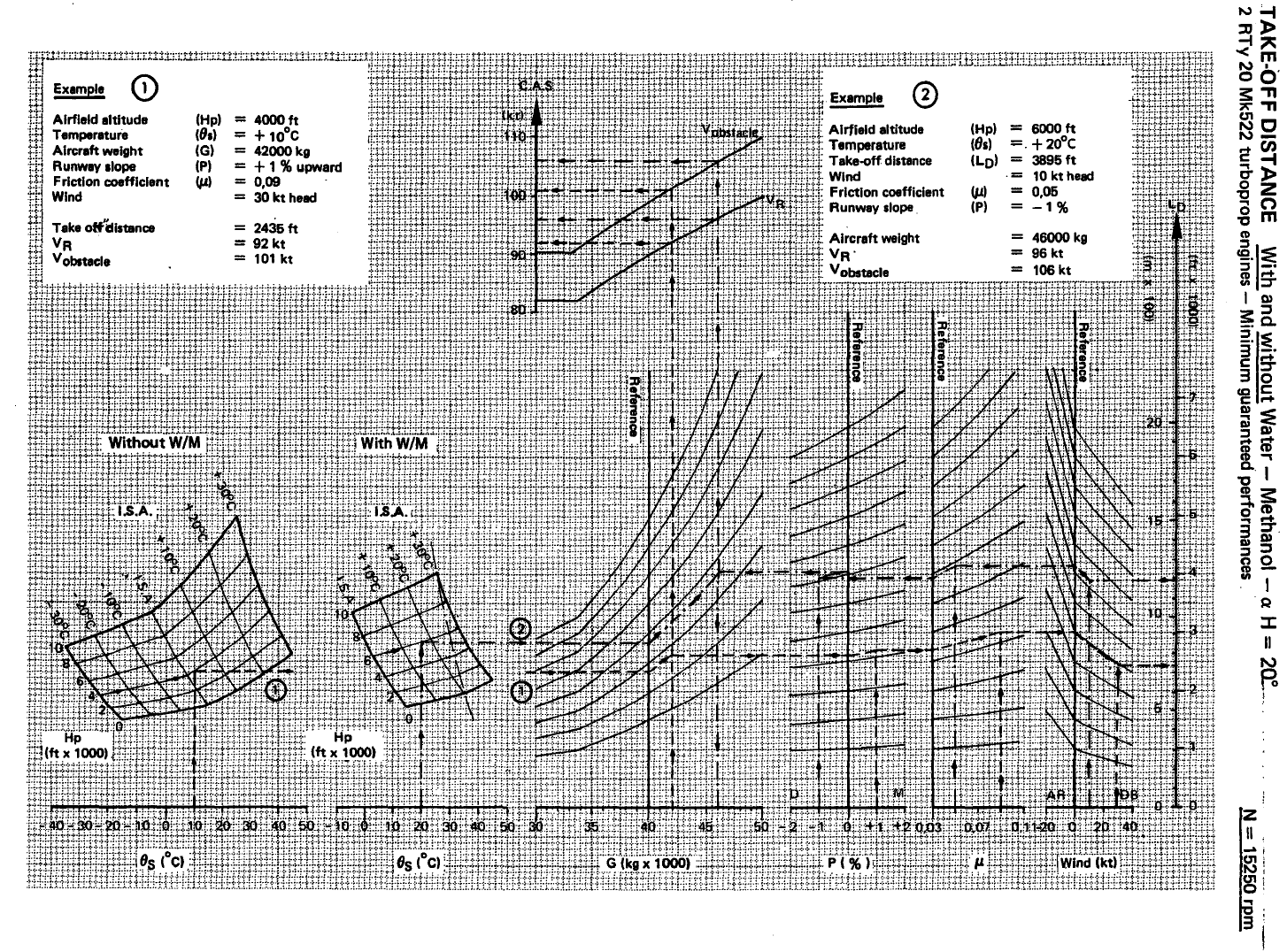
Following charts indicate normal takeoff speed and distance with 20 degrees of flaps.
Takeoff distance includes horizontal distance required to take-off plus climb to a 50 feet clearance height.
Takeoff is performed with full throttle; illustration covers use and non-use of water-methanol injection system.
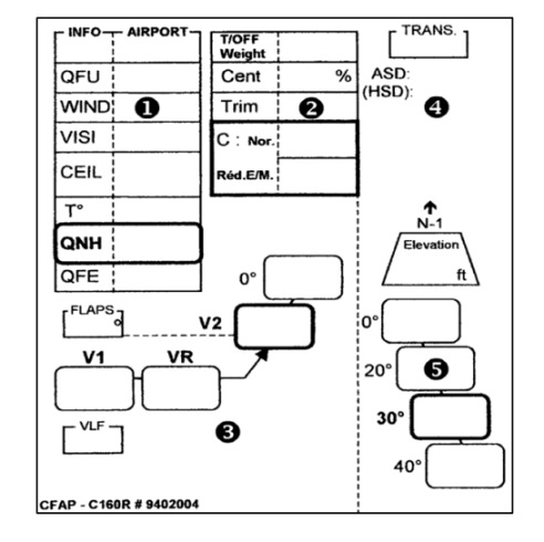
During aircraft operation, a “take-off card” is placed in the field of view of the full crew, gathering essential information for the take-off.
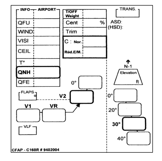
It is completed with the following steps:
-
Airport OACI code and information based on weather: QFU, wind, visibility, ceiling, temperature, QNH.
-
Take-off weight, corresponding trim calculated and take-off power (with or without water-methanol injection).
-
Flaps setting and corresponding reference speeds: V1, VR, V2.
-
Transition altitude, potential return to take-off airport procedure.
-
Landing speeds in case of return.
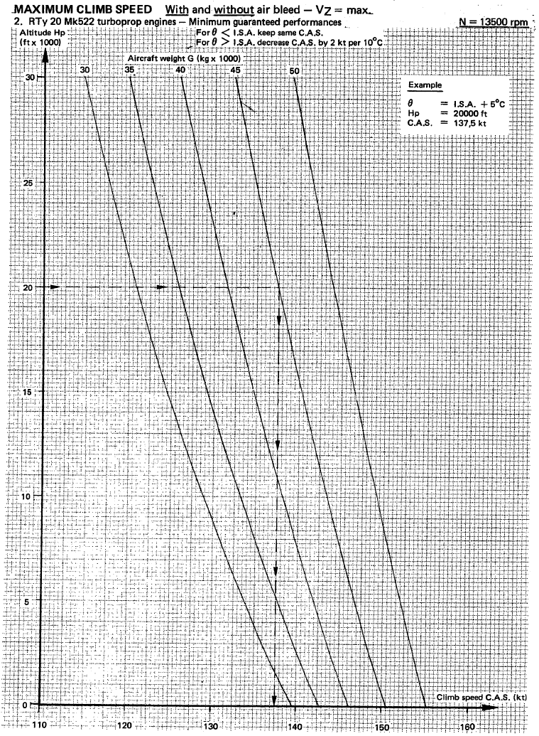
Climb
Maximum climb speed with and without air bleed.
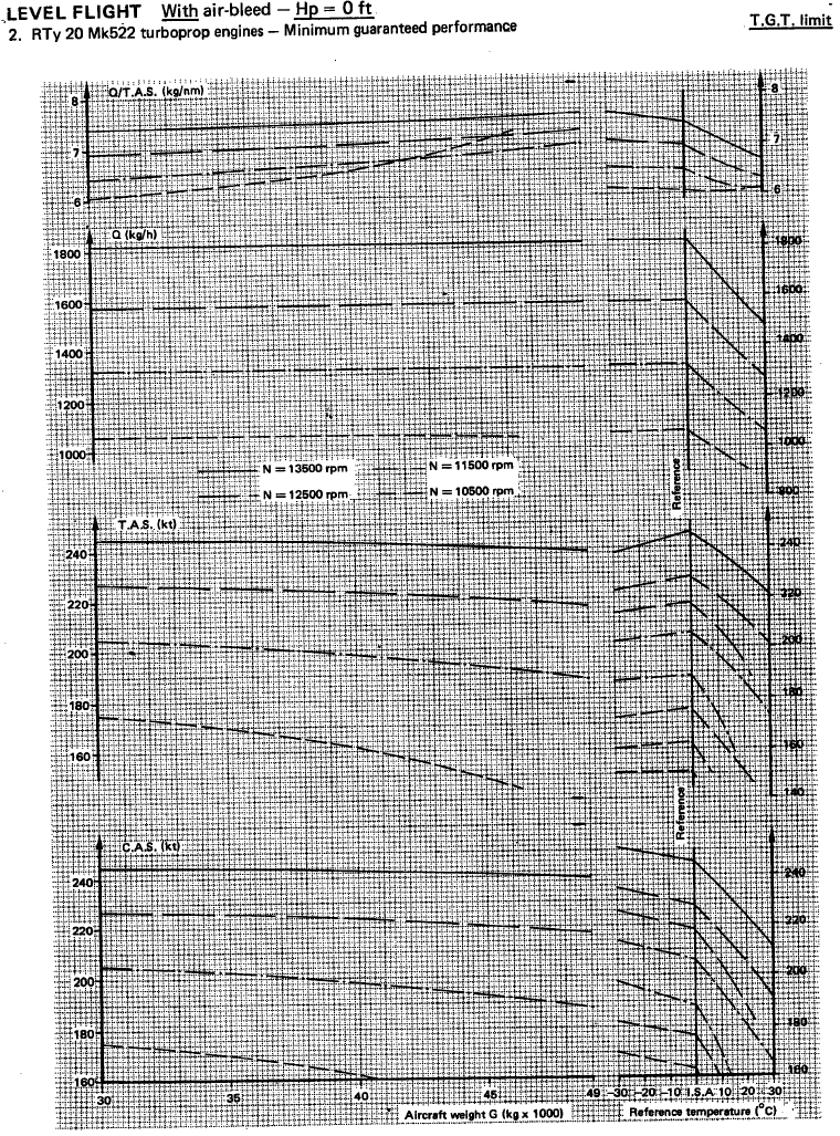
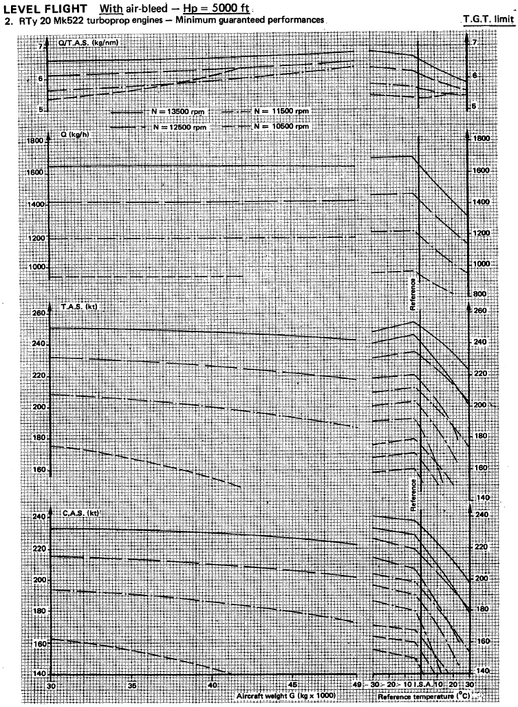
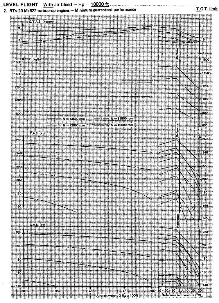
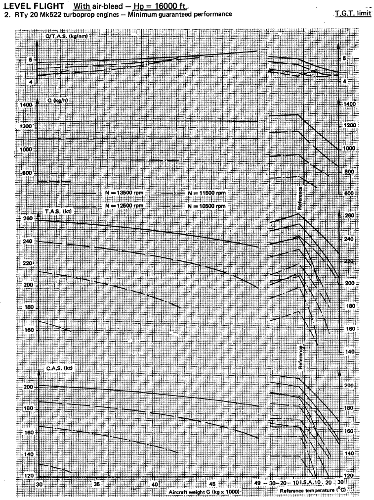
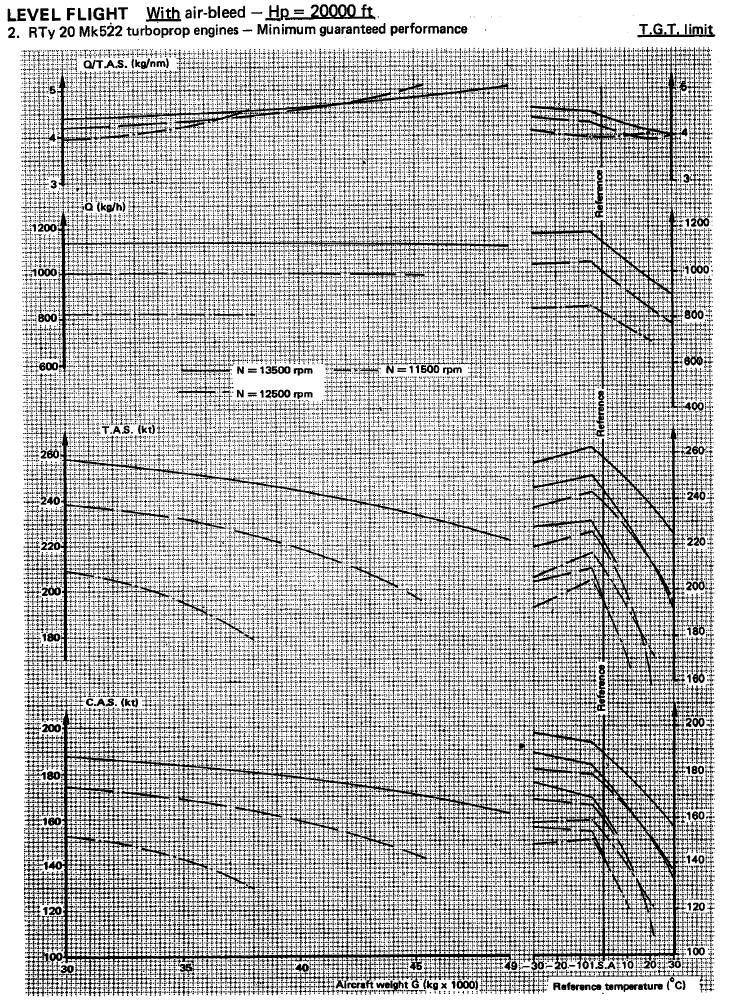
Cruise
Each following chart corresponds to a given altitude.
It shows true airspeed and fuel consumption for various N1 values, with air bleed.
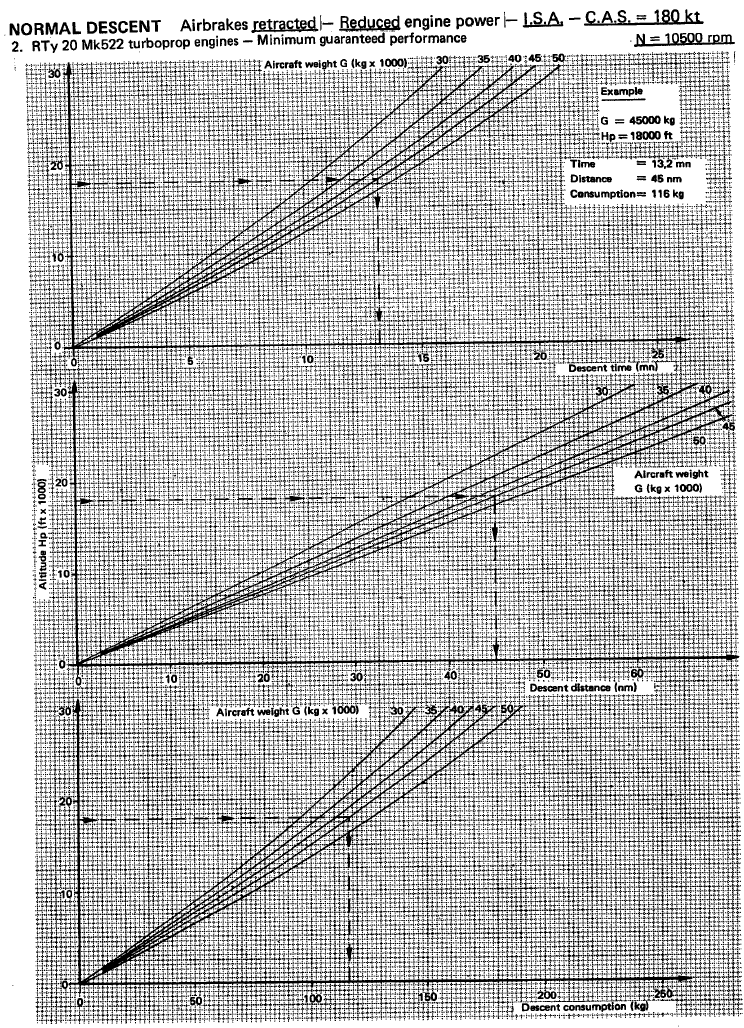
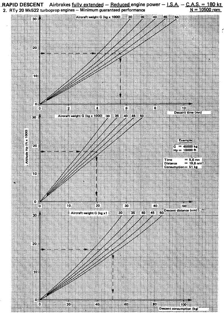
Descent
Two types of descents are presented in following charts:
-
Normal descent with airbrakes retracted.
-
Rapid descent with airbrakes extended.
In both cases, a speed of 180 knots is targeted.
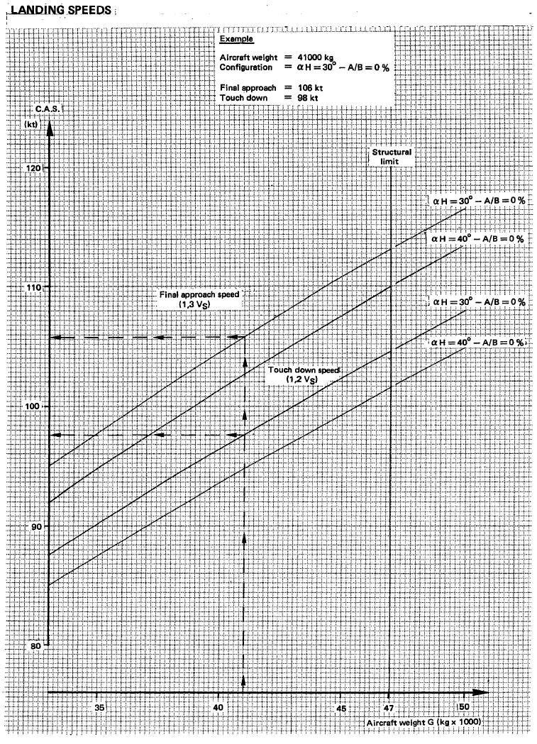
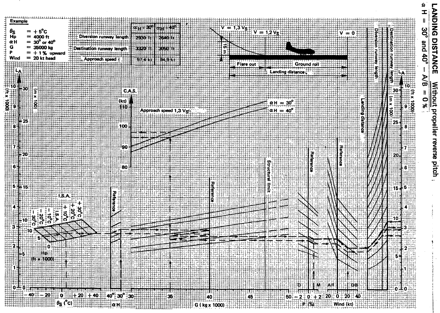
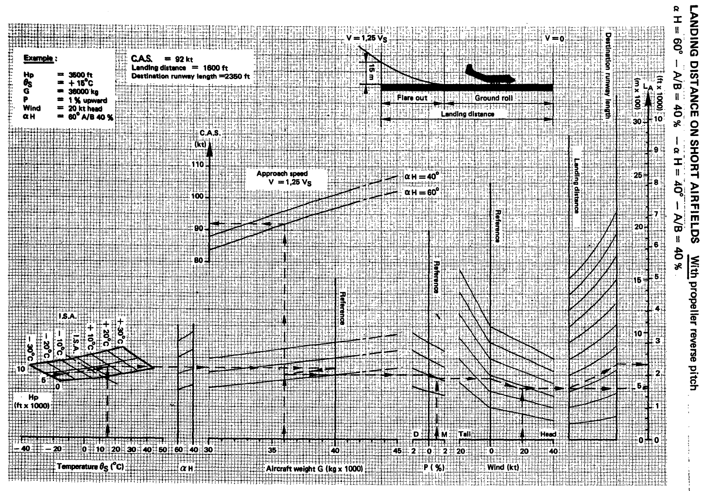
Landing
Following charts indicate normal landing speed and distance with different flaps settings.
Two scenarios are provided:
-
Normal landing without airbrakes (A/B) and without reverse.
-
Short field landing with 40% airbrakes and reverse.
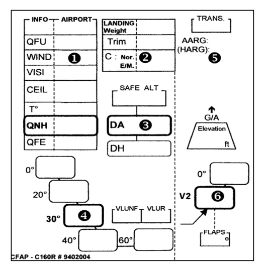
Similarly to the take-off card, a landing card is filled with essential information related to the landing.
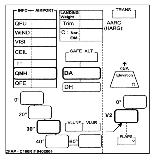
It is completed with the following steps:
-
Airport OACI code and information based on weather: QFU, wind, visibility, ceiling, temperature, QNH.
-
Landing weight and corresponding trim calculated.
-
Security altitude, decision height and corresponding altitude.
-
Landing speeds depending on flaps setting.
-
Missed approach procedure, with transition altitude and details of the go-around procedure.
-
Go-around speed and flaps setting.