General description
Characteristics
General performance
The Rafale combines fighter-level agility with a payload and fuel fraction usually associated with heavier aircraft. This balance is one of the key reasons it can remain effective in both air-to-air and air-to-surface roles without changing airframe family.
Depending on the variant, empty mass remains around the 10-ton class: roughly 9,350 kg for the C, 9,550 kg for the B, and 9,950 kg for the M. Maximum takeoff weight reaches 24.5 t, while internal fuel reaches about 4.7 t, with a reduction on the two-seat B. External fuel can add up to 4.8 t (with three big fuel tanks), which gives the aircraft a wide range of usable mission profiles from short-range interception to long-range strike or ferry transit.
In speed terms, the aircraft can reach up to Mach 1.8 at altitude and about 750 kt at low level. It also retains strong acceleration and high subsonic or transonic performance even in operational loadouts, which is central to its omnirole concept.
At the other end of the envelope, handling remains unusually favorable for an aircraft of this size and mass. Approach speed is typically around 130 kt, and low-speed controllability remains one of the defining strengths of the type. Combined with its load-factor limits and high roll performance, this gives the aircraft a broad usable envelope rather than just a high top speed.
| Length | 15.30 m |
| Wingspan | 10.90 m |
| Height | 5.30 m |
| Empty weight | 9,350 kg |
| Maximum takeoff weight | 24,500 kg |
| Internal fuel | 4,700 kg |
| External fuel | Up to 4,800 kg |
| External load capacity | 9,500 kg |
| Maximum speed (altitude) | Mach 1.8 |
| Maximum speed (low level) | 750 kts |
| Service ceiling | 50,000 ft |
| Limit load factors | -3.2 G / +9 G |
Airframe and aerodynamic layout
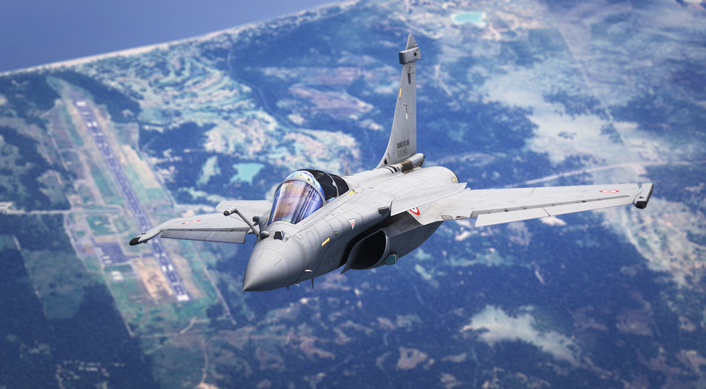
The Rafale is a twin-engine, close-coupled canard-delta aircraft. This layout is one of the defining features of the type and drives much of its handling, payload flexibility, and mission performance.
The main delta wing provides both lifting area and internal volume, while the close-coupled canards improve pitch authority and help maintain lift and controllability at high angle of attack. In broad terms, this gives the aircraft strong maneuvering capability without sacrificing range or heavy-store carriage.
Digital fly-by-wire is an essential part of the overall aerodynamic concept. It allows the aircraft to exploit the full benefit of the configuration while preserving precise handling and flight safety throughout the envelope. In practice, the pilot experiences a highly responsive aircraft rather than having to manage the raw aerodynamic compromises directly.
All three operational variants share the same core aerodynamic philosophy and a very high level of structural commonality.
The airframe is also designed with signature reduction in mind. Without turning the Rafale into a dedicated stealth aircraft, its shapes and selected materials help reduce detectability, while still preserving access, robustness, and external-store capacity.
Our approach
Developing a faithful Rafale simulation within Microsoft Flight Simulator required a number of significant technical choices.
One of the most important decisions was to completely override the default MSFS flight model. While the simulator provides a capable general-purpose flight dynamics engine, it is not sufficient to accurately reproduce the unique handling characteristics and flight control laws of the Rafale. To achieve the level of fidelity we were aiming for, we implemented our own flight control system and fly-by-wire (FBW) logic entirely in WASM.
Beyond improving flight dynamics accuracy, this custom FBW architecture also enabled us to implement advanced aircraft-specific features such as automatic terrain following and autothrottle control in angle-of-attack mode.
The aircraft's avionics are implemented using a combination of WASM and JavaScript technologies. This hybrid architecture allows us to combine high-performance systems simulation with smooth and responsive cockpit displays.
As development progressed, we increasingly leveraged the new capabilities introduced with Microsoft Flight Simulator 2024. These new APIs and systems enabled us to implement features that would have been difficult or impossible to achieve in previous versions of the simulator.
Throughout the project, we have continuously pushed the simulator beyond its original design boundaries. In many areas, we are effectively operating at the limits of what the platform currently allows. As a result, despite extensive testing, some bugs or unexpected behaviors may still be encountered. We appreciate your understanding and feedback as we continue to refine and improve the simulation.
Cockpit layout
Main panel
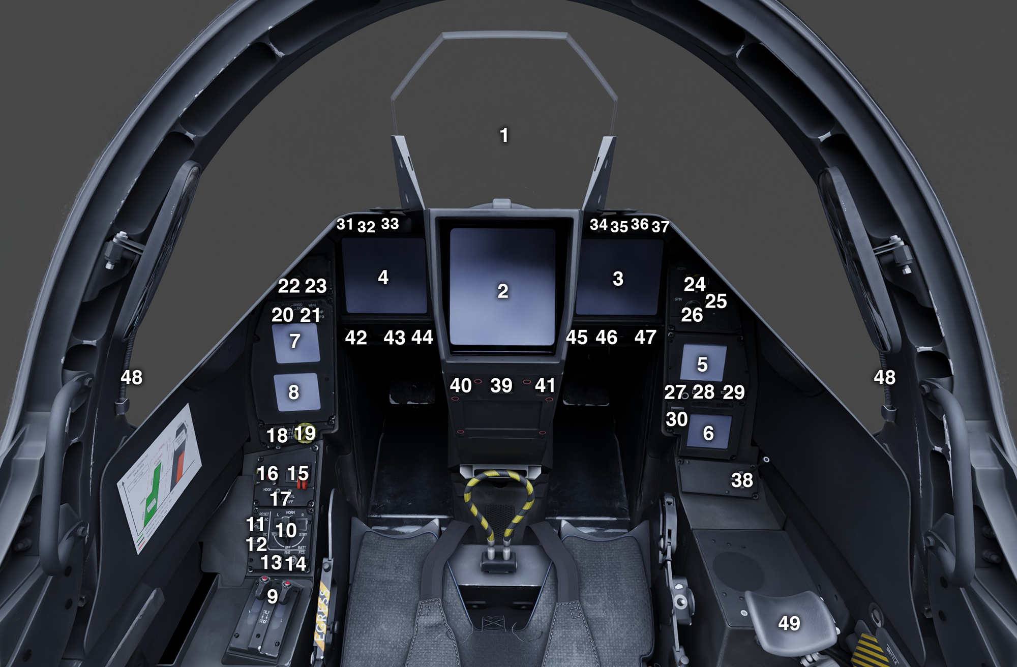
| # | Description | # | Description |
|---|---|---|---|
| 1 | Head-up Display (HUD) | 26 | RLD Visualization Knob |
| 2 | Head Center Display (HCD) | 27 | Baro Setting Knob |
| 3 | Right Lateral Display (RLD) | 28 | Altimeter STD Button |
| 4 | Left Lateral Display (LLD) | 29 | IPS Test Button |
| 5 | IPS | 30 | De-Ice Button & Indicator |
| 6 | IMC | 31 | Terrain Following Indicator |
| 7 | PDS1 | 32 | Auto Guidance Indicator |
| 8 | PDS2 | 33 | EFB (Tablet) Button |
| 9 | Auxiliary Engine Control | 34 | Unused |
| 10 | 5K Selector / APU Button / ECS Button | 35 | Left Engine Fire Indicator |
| 11 | AC Circuit Rearm Button | 36 | APU Fire Indicator |
| 12 | DC Circuit Rearm Button | 37 | Right Engine Fire Indicator |
| 13 | Engines Calculators Rearm Button | 38 | RLD Page Selection Switch |
| 14 | Flight Control System Rearm Button | 39 | HCD Declutter Button |
| 15 | Landing Gear Handle & Indicator | 40 | HCD Map Opacity Knob |
| 16 | Tailhook Button & Indicator | 41 | HCD Brightness Knob |
| 17 | Refuel Switch | 42 | PDS 2 Brightness Knob |
| 18 | Stores Handling Mode Switch | 43 | PDS1 Brightness Knob |
| 19 | Emergency Stores Jettison Button | 44 | RLD Brightness Knob |
| 20 | Multi-Function Knob (MFK) | 45 | LLD Brightness Knob |
| 21 | LLD Page Selection Switch | 46 | IPS Brightness Knob |
| 22 | Master Weapons Switch | 47 | IMC Brightness Knob |
| 23 | LLD Visualization Knob | 48 | Map Lights |
| 24 | Spin Switch | 49 | Movable Armrest |
| 25 | Automatic Recovery Button |
HOTAS (stick)
The HOTAS (Hands On Throttle And Stick) philosophy allows the pilot to perform nearly all essential flight and combat operations without removing their hands from the throttle and control stick. This significantly reduces workload and improves situational awareness, particularly during demanding phases of flight.
While we have implemented a large portion of the aircraft's HOTAS functionality, some controls are not available due to limitations or missing features within the simulator itself.
The list of available bindings is here.
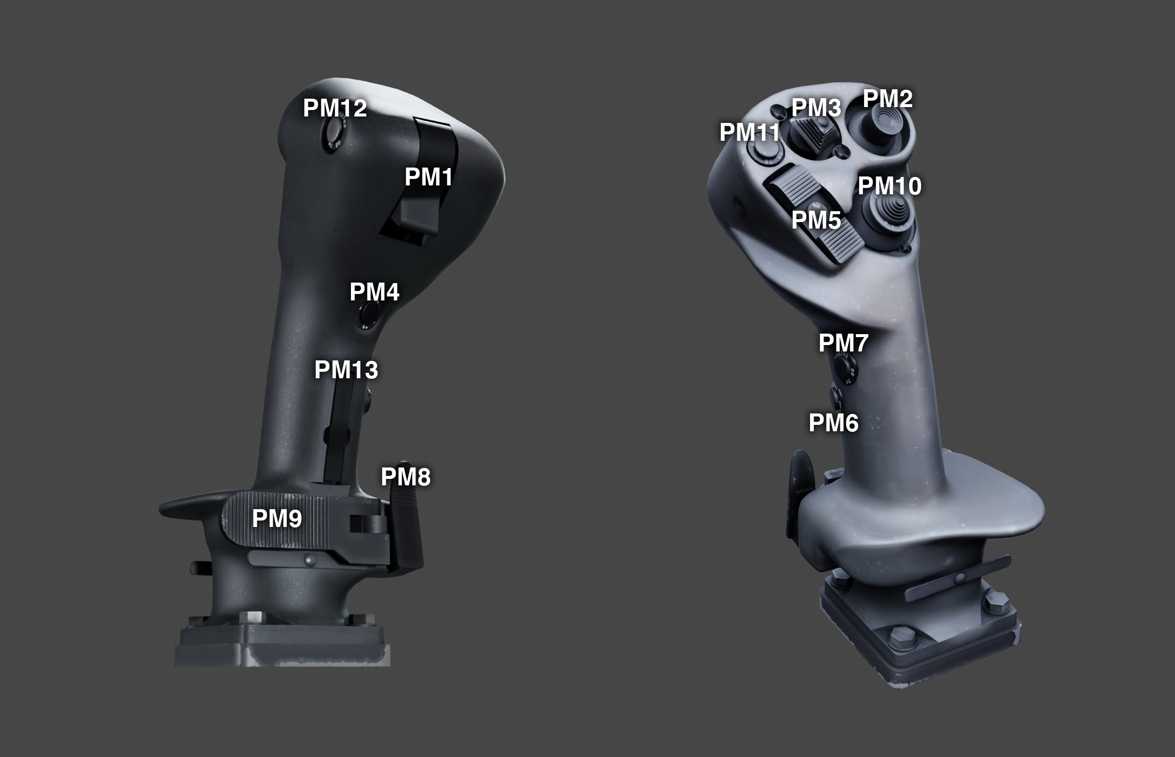
| # | Description | # | Description |
|---|---|---|---|
| PM1 | Weapon Fire | PM8 | Autopilot Engage / Nose Wheel Steering Toggle |
| PM2 | INOP | PM9 | Autopilot Disengage |
| PM3 | Autopilot Attitude / Trim Hat Switch | PM10 | LLD System Page / DAS Assign Button / Primary Mode Page |
| PM4 | INOP | PM11 | LLD Autopilot Page Button |
| PM5 | INOP | PM12 | INOP |
| PM6 | INOP | PM13 | INOP |
| PM7 | INOP |
HOTAS (throttle)
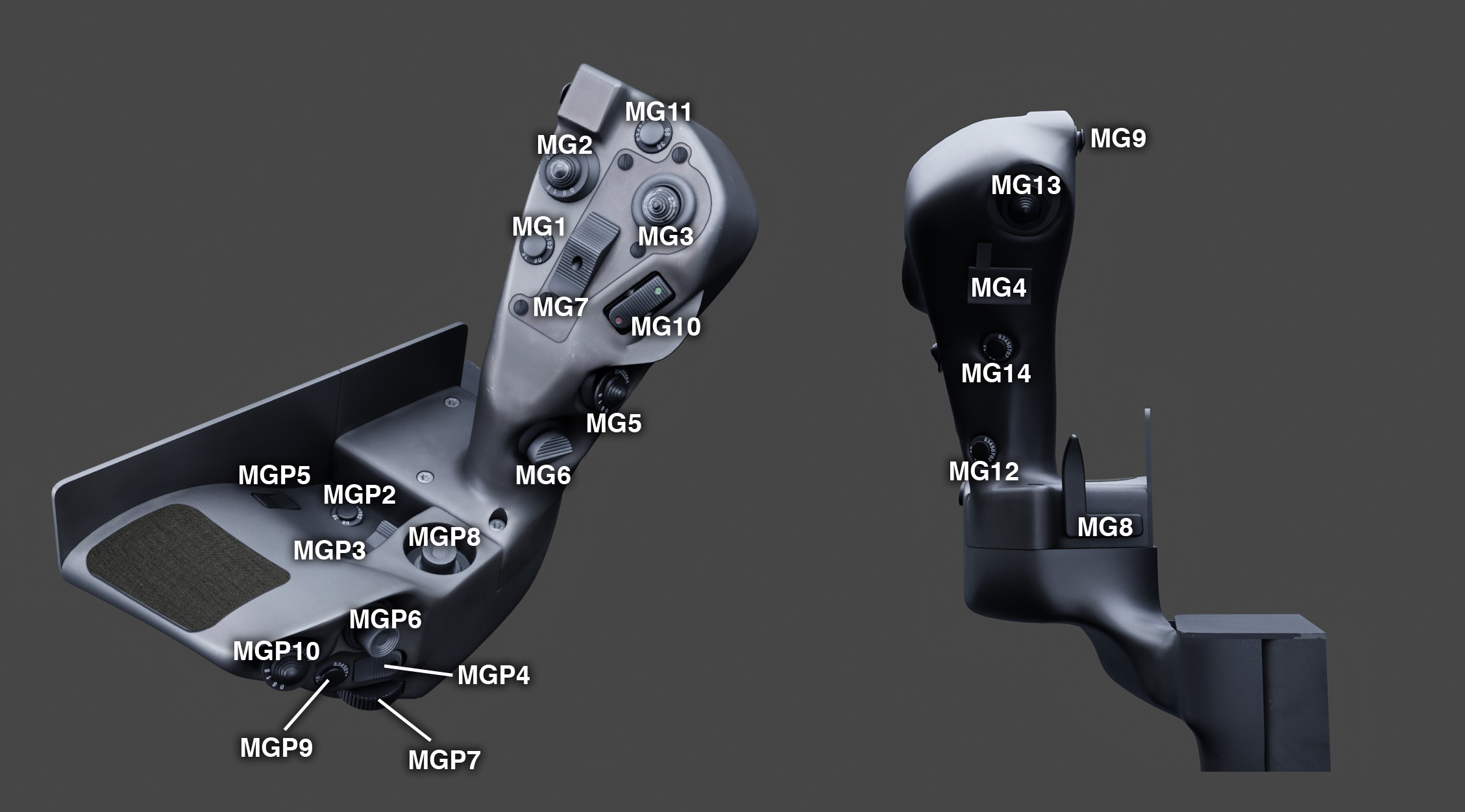
| # | Description | # | Description |
|---|---|---|---|
| MG1 | Combat Mode Selection | MG13 | INOP |
| MG2 | INOP | MG14 | INOP |
| MG3 | INOP | MGP2 | INOP |
| MG4 | Target Designation | MGP3 | HCD Map Zoom |
| MG5 | INOP | MGP4 | Create MRK goal |
| MG6 | Combat Mode Selection | MGP5 | INOP |
| MG7 | Spoilers Switch | MGP6 | INOP |
| MG8 | Autothrottle Toggle | MGP7 | INOP |
| MG9 | Flares Button | MGP8 | INOP |
| MG10 | INOP | MGP9 | INOP |
| MG11 | HUD Drift Cut-Out Button | MGP10 | Taxi / Landing / Police Lights Switch |
| MG12 | INOP |
Left console
The controls located in the colored panel areas are dedicated to abnormal and emergency procedures. They are protected by a cover and are generally not used during normal flight operations.
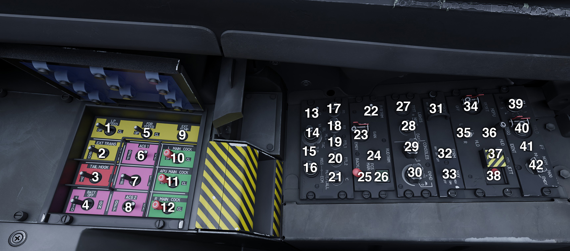
| # | Description | # | Description |
|---|---|---|---|
| 1 | Low Pressure Crossfeed Valve Switch | 23 | FCS Gain Switch |
| 2 | External Fuel Transfer Switch | 24 | Rudder Trim Switch |
| 3 | Tailhook Emergency Switch | 25 | FCS Mode Switch |
| 4 | Emergency Battery Switch | 26 | FCS Digital Mode Indicator |
| 5 | Feed Tanks Crossfeed Valve Switch | 27 | Fire Alarms Test Switch |
| 6 | Left Generator Switch | 28 | Indicators Intensity Knob |
| 7 | Transformer Toggle Switch | 29 | Upper: Map Lights Knob Lower: Console Lights Knob |
| 8 | Right Generator Switch | 30 | Upper: Backlight Intensity Knob Lower: INOP |
| 9 | External Fuel Dump Button | 31 | Strobe Lights Switch |
| 10 | Left Engine Main Cock Switch | 32 | Formation Lights Switch |
| 11 | APU Main Cock Switch | 33 | Navigation Lights Switch |
| 12 | Right Engine Main Cock Switch | 34 | MDPU Reset Switch |
| 13 | INOP | 35 | LD Reset Switch |
| 14 | INOP | 36 | HUD / HCD Reset Switch |
| 15 | INOP | 37 | Selective Jettison Hood |
| 16 | INOP | 38 | Selective Jettison Button |
| 17 | COM1 Volume Knob | 39 | IFF Key Knob |
| 18 | COM2 Volume Knob | 40 | IFF Hold/Unhold Switch |
| 19 | DTL1 Volume Knob | 41 | IFF Ident Button |
| 20 | DTL2 Volume Knob | 42 | IFF Mode Selection Knob |
| 21 | Intercom Volume Knob | ||
| 22 | Pitch / Roll Trim Switch |
Right console
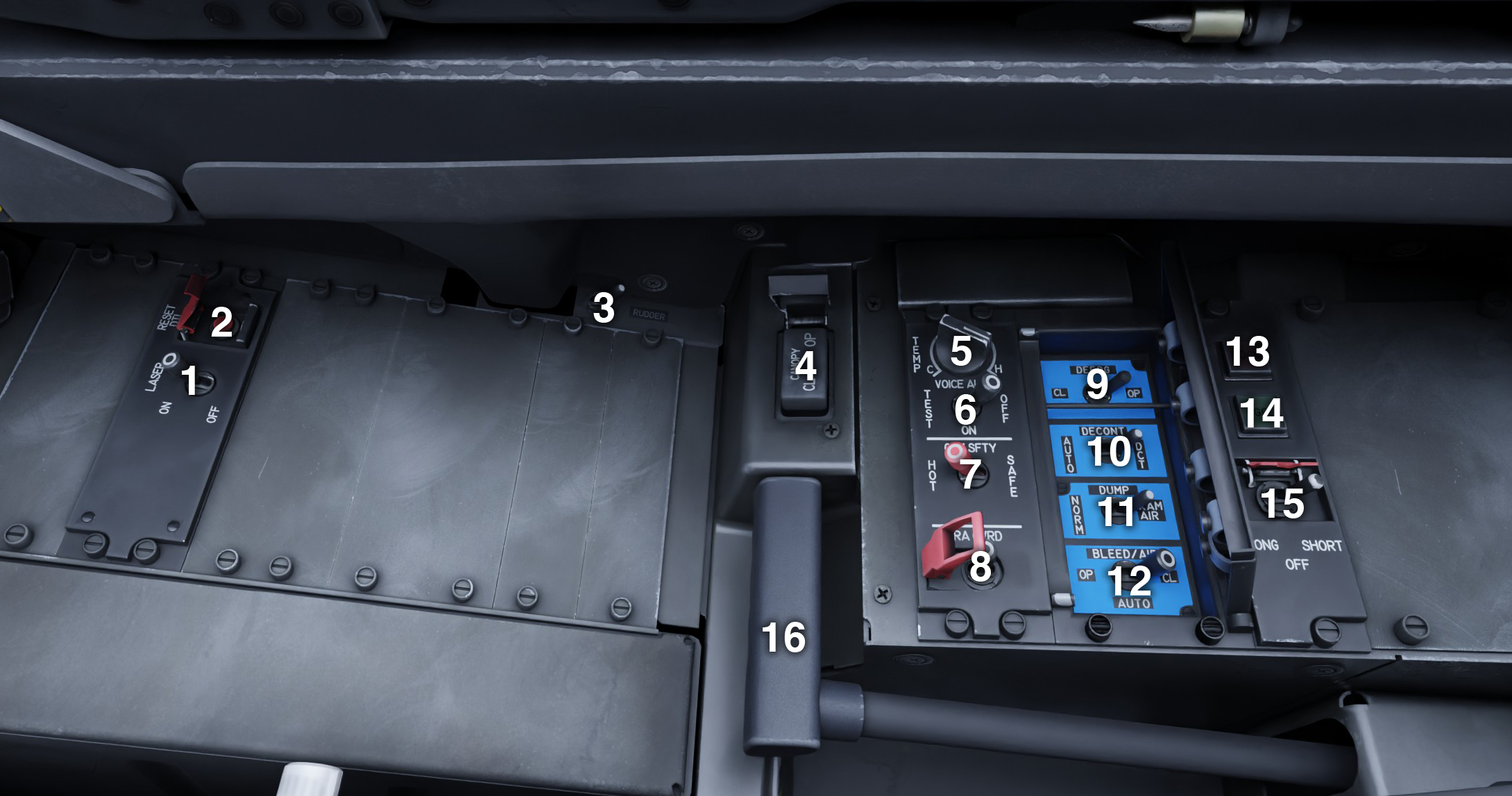
| # | Description | # | Description |
|---|---|---|---|
| 1 | Laser Switch INOP | 9 | Defog Valve Switch |
| 2 | Reset DTL Button INOP | 10 | Air Decontamination Switch |
| 3 | Rudder Pedals Setting Switch | 11 | Depressurization Mode Switch |
| 4 | Canopy Switch | 12 | Bleed Air Valve Mode Switch |
| 5 | Cabin Temperature Knob | 13 | FCS Test NOGO Indicator |
| 6 | Aural Alerts & Indicators Test Switch | 14 | FCS Test GO Indicator |
| 7 | General Safety Switch | 15 | FCS Test Switch |
| 8 | Radio Alt Override Switch | 16 | Parking Brake Handle |