General
Circuit description
Like most modern fighter aircraft, the Rafale features a complex electrical network divided into multiple AC and DC buses to ensure redundancy and fault tolerance.
Under normal operating conditions, the pilot has virtually no actions to perform regarding the electrical system, as it is managed automatically through the 5K selector.
The current state of the electrical system can be monitored on the LD MISC page.
Battery
The aircraft is equipped with a 24 V battery.
Although the battery can power essential systems, the aircraft is normally connected to an external power source before engine start so that onboard systems can operate without discharging the battery.
The battery can be manually forced ON or OFF in abnormal situations using the Emergency Battery Switch.
Generators
Each engine drives an electrical generator (ACG1 and ACG2) rated in the 30–40 kVA power range.
The APU is also equipped with a smaller generator used to support the electrical system during autonomous starts before the main engine generators become available.
Generators are automatically connected to the electrical network when available and require no pilot action. Two emergency switches allow the pilot to disconnect ACG1 and ACG2 if needed.
AC circuit
The AC network is organized around three buses:
BUS AC1, normally powered byACG1.BUS AC2, normally powered byACG2.BUS AC EXT, powered by the GPU or APU generator and acting as an interconnection bus betweenBUS AC1andBUS AC2.
DC circuit & shed bus
The DC network supplies power to most aircraft systems.
It is divided into two buses:
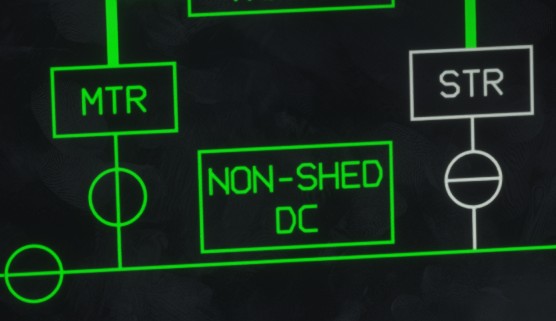
BUS DC NON-SHED, which powers systems normally available whenever electrical power is present.BUS DC SHED, which powers non-essential equipment that may be automatically disconnected in specific situations to reduce electrical load and preserve battery capacity.
During an autonomous start, placing the 5K selector in the STBY position keeps the BUS DC SHED bus disconnected. Only essential equipment remains powered. As a result, most avionics displays remain off except for the left lateral display.
Transformer rectifiers
The interface between the AC and DC networks is provided by two transformer rectifiers that convert AC power into a regulated 24 V DC supply:
MTRconnected toBUS AC1and normally used during standard operation.STRconnected toBUS AC2and used as a backup ifMTRbecomes unavailable.
Selection between both transformer rectifiers is controlled using the Transformer Toggle Switch.
Ground power
During most ground operations, the Rafale is supplied by a Ground Power Unit (GPU), which provides external AC power.
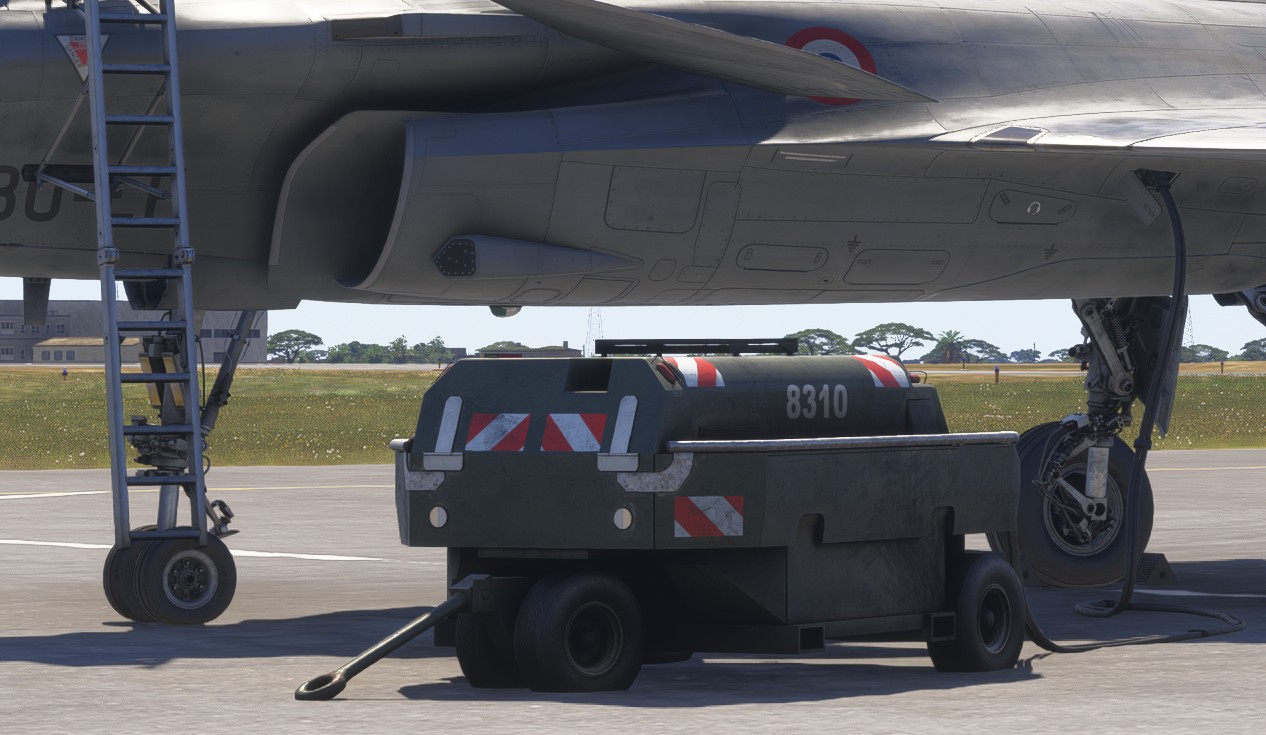
The GPU can be connected either from the EFB tablet or during the walkaround inspection after opening the external power receptacle access panel.
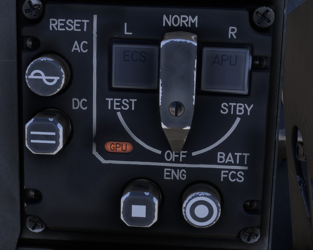
When connected, the entire aircraft electrical network is powered, even when the 5K selector is in the OFF position.