Principles
The avionics are organized around four main displays and four auxiliary displays:
- The head-up display (
HUD) is always within the pilot’s field of view. It shows key flight parameters as well as mission-related information. - The head center display (
HCD) is collimated and positioned directly in front of the pilot. It primarily shows a map with tactical information. - The two lateral displays (
LLD&RLD) show various selectable pages. PDS1is used to select the primary mode and the pages shown on the lateral displays.PDS2displays the active autopilot modes and IFF information.IPSis a backup artificial horizon.IMCshows essential fuel and engine information.
The center display, the two lateral displays and PDS1 are touch-screens while the others are not clickable.
In the real aircraft, the center display is not clickable and the pilot is using a touchpad to interact with it. As this kind of interaction is not really operable in the simulator, we decided to make the screen clickable.
Primary mode
One of the key concepts in the aircraft is the primary mode. This term is used frequently throughout the documentation.
There are four primary modes, each corresponding to a different task:
A/A: air-airA/S: air-surfaceAPP: approachUPD: update
Depending on the active primary mode, the aircraft allocates its systems and sensors accordingly.
On the single-seat variant (Rafale C), only one mode can be selected at a time, meaning that selecting a mode will unselect all the other ones.
APP mode is specifically used during approach, and is automatically selected when the landing gear is extended.
UPD mode is used in flight, at regular intervals, and depending on the mission, to realign the inertial navigation system (INS).
Although the INS and its initial alignment are simulated, in-flight realignment through UPD mode has no practical use in this add-on, as the underlying realignment process is very complex and is not simulated for now.
Multi-function knob
The MFK provides quick access to some of the aircraft's most frequently used settings.
The outer ring is used to select the setting, while the inner ring is used to adjust its value.
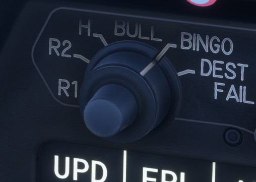
When a value is being adjusted, the selected setting and its current value are displayed in a box in the bottom-right corner of the HUD.
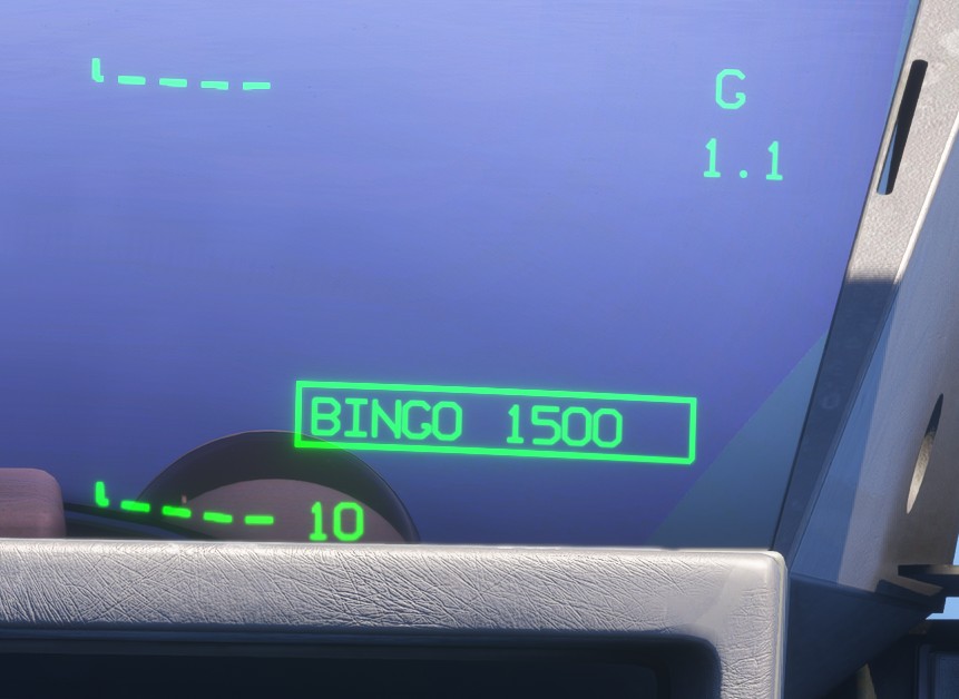
Press the outer ring to confirm the selected value. When using a mouse, this is performed with a right-click. If no adjustment is made for a few seconds, the box automatically disappears from the HUD.
The knob has seven positions, although only six labels are shown around it:
-
R1: adjusts the Radio 1 (COM 1) frequency. -
R2: adjusts the Radio 2 (COM 2) frequency. -
H: adjusts the safety height, or the decision height whenAPPmode is active. -
BULL: changes the bullseye reference. -
BINGO: adjusts the BINGO fuel value. -
DEST: changes the active destination waypoint. See the flight plan section. -
ALT: adjusts the autopilot target altitude (ALTSEL).
When the selected altitude is changed using the MFK, ALTSEL mode is automatically engaged if the autopilot is active.