Head-up display
Description
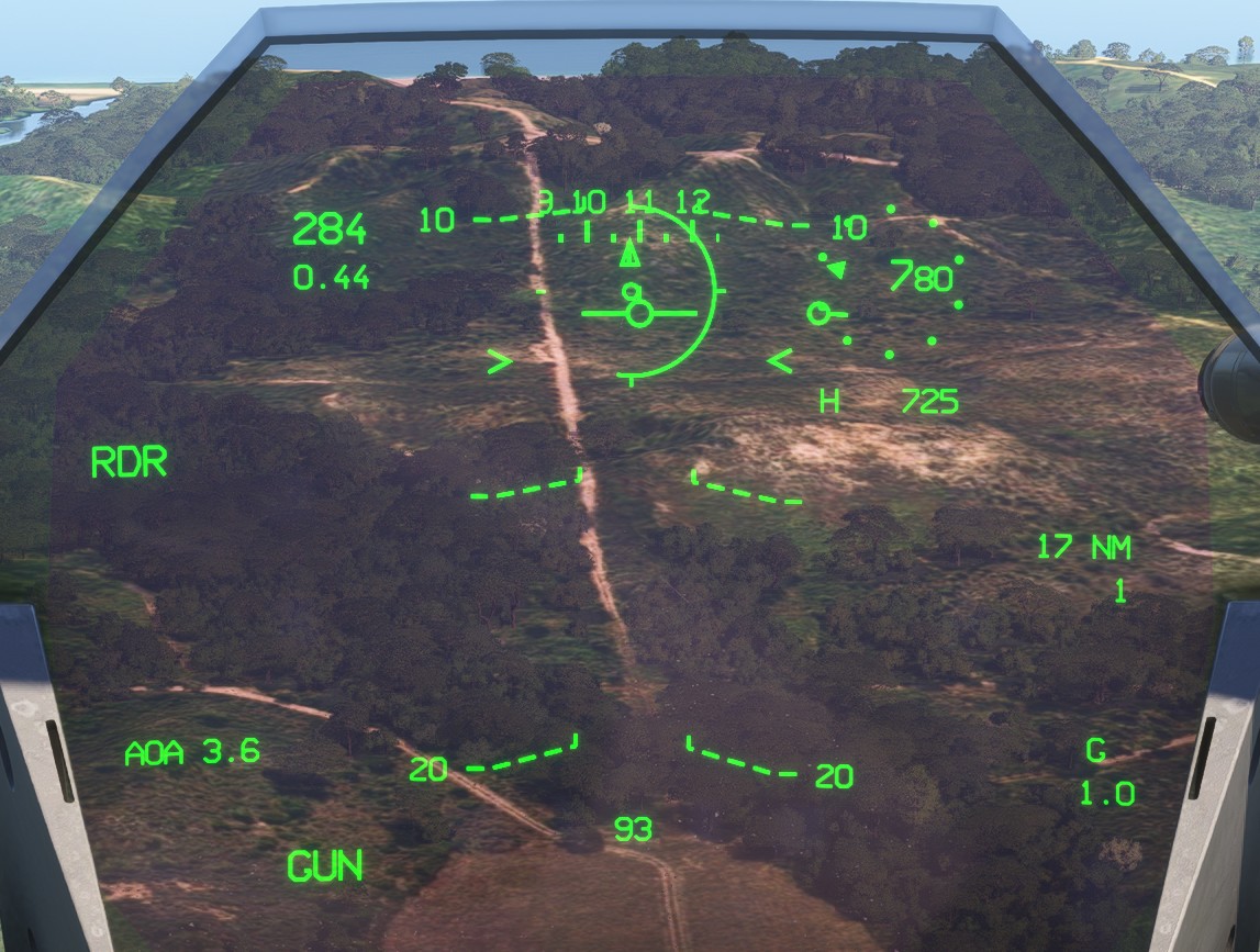
The head-up display centralises the information required to fly the aircraft in all operating conditions.
It is the pilot's primary visual reference, as it remains within the forward field of view.
Common display
Essential flight information remains visible regardless of the selected mode.
Pitch ladder
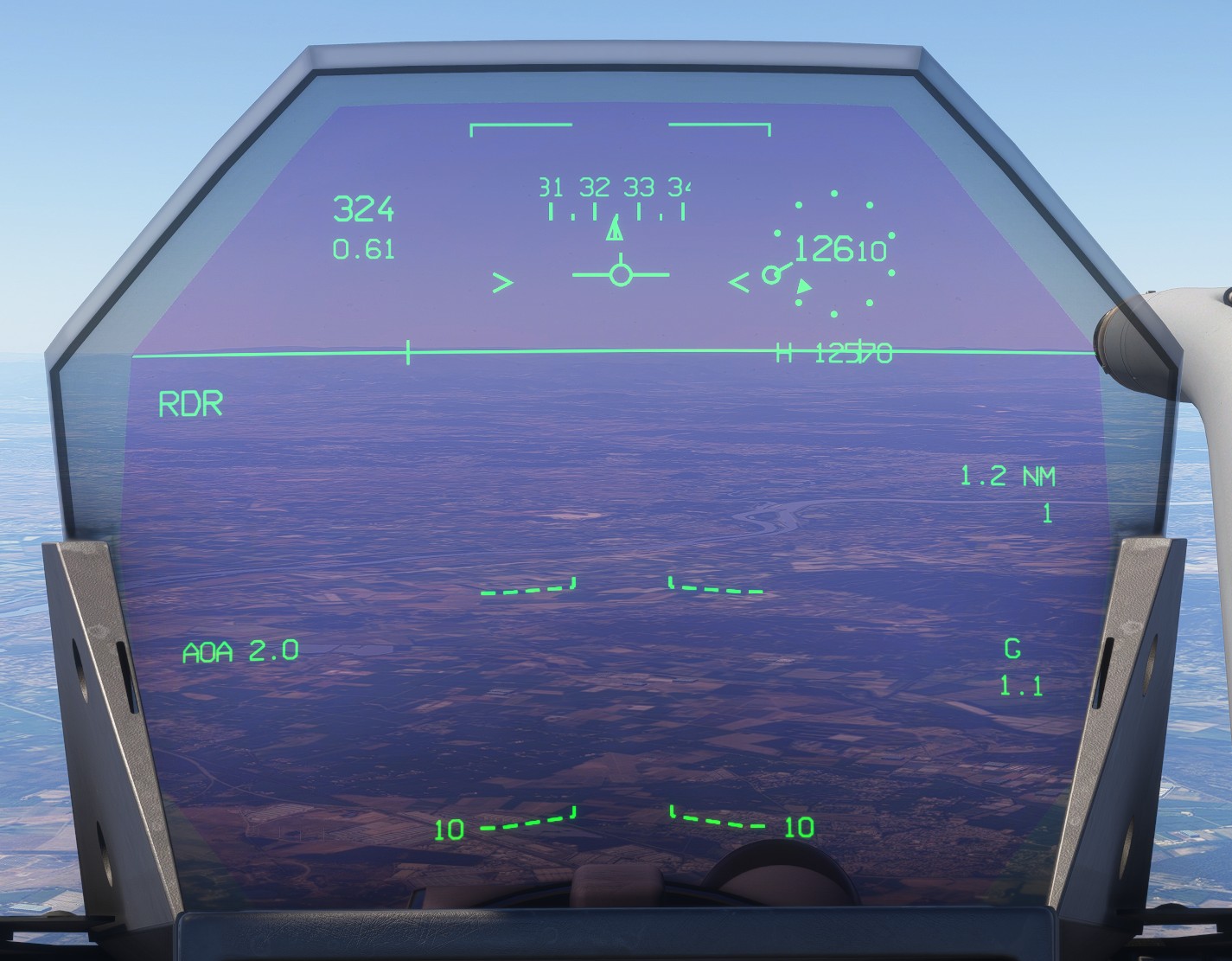
The pitch ladder is organised around a continuous line aligned with the horizon.
Pitch is graduated every five degrees in both directions, with numerical labels every ten degrees.
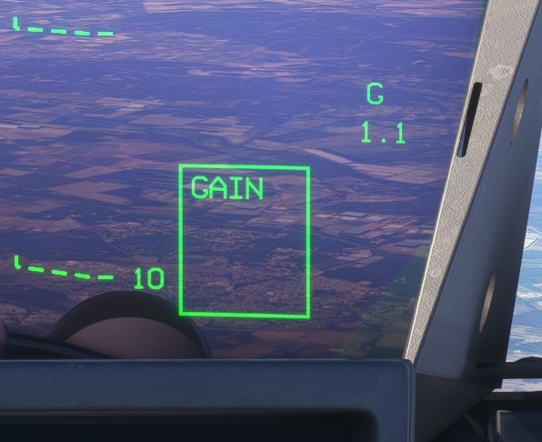
Negative pitch lines are dashed and become progressively more vertical as the nose-down attitude increases, helping the pilot recognise an increasing descent angle towards the ground.
VVI
The velocity vector indicator (VVI) represents the aircraft's current flight path.
It can be interpreted as the projected point towards which the aircraft is moving.
On the Rafale HUD, the VVI remains horizontally centred relative to the pitch ladder. The ladder moves laterally to indicate aircraft drift.
Drift indication can be disabled using the drift cut-out function on the MG11 button. This may be useful during approaches in strong crosswinds.
The VVI uses a specific symbol when the landing gear is down and locked.


Speed
Indicated airspeed is displayed in the upper-left corner, with a minimum displayed value of 30 knots.
The Mach number is displayed immediately below and appears only from Mach 0.4 onwards.
Altimeter
Aircraft altitude is displayed in feet inside a circular scale graduated in 100-foot increments.
The barometric setting appears below the altitude value while it is being adjusted using the Baro Setting Knob.
The STD indication remains displayed when standard pressure is selected.
Radio height
Radio height is displayed below the altimeter next to an H.
It disappears above 13,000 feet or when the aircraft pitch or bank angle becomes excessive, preventing the system from calculating a reliable value.
Longitudinal acceleration
The longitudinal acceleration brackets > < are displayed on either side of the VVI and move vertically according to the aircraft's acceleration or deceleration.
When the brackets are below the VVI, the aircraft is losing speed.
Their movement is limited to the visible area of the HUD.
When an engine is operating in afterburner, a second bracket appears on the corresponding side, changing > < into >> <<.
AOA and G-meter
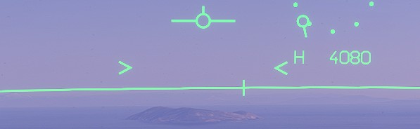
The angle of attack, expressed in degrees, is continuously displayed on the left and identified by AOA.
The current load factor is displayed on the right and identified by G.
Heading indication
A heading ribbon is displayed along the top of the HUD. It shows the aircraft heading and track using either magnetic or true references, depending on the LD HSI setting.
A vertical line indicates the heading, while the triangle indicates the track.

The horizon line is also graduated every ten degrees.
Alerts & alarms
The HUD repeats any active alerts or alarms, as described in the alarms section.
The only alert specific to the HUD, and therefore not shown on the other displays, is the safety height alert.
Level 2 alerts are displayed as flashing text in the upper-centre area of the HUD.
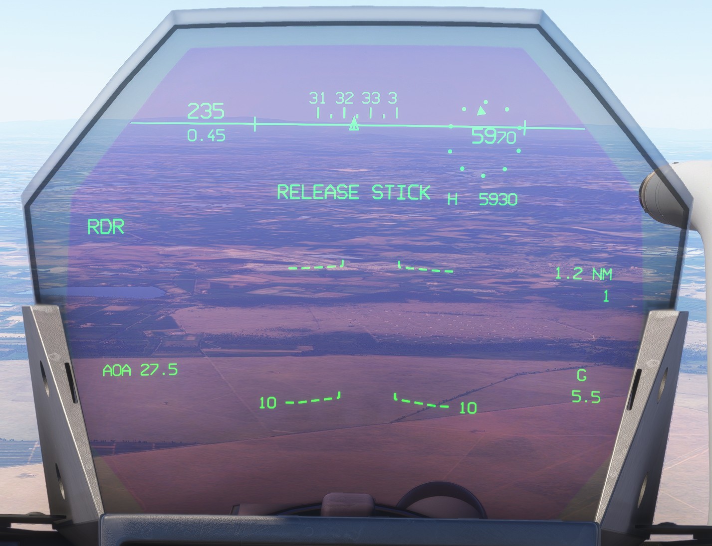
Alarms are displayed inside a box in the lower-right corner.
Takeoff display
The takeoff display supplements the standard flight information with dedicated references for the ground roll and initial climb.
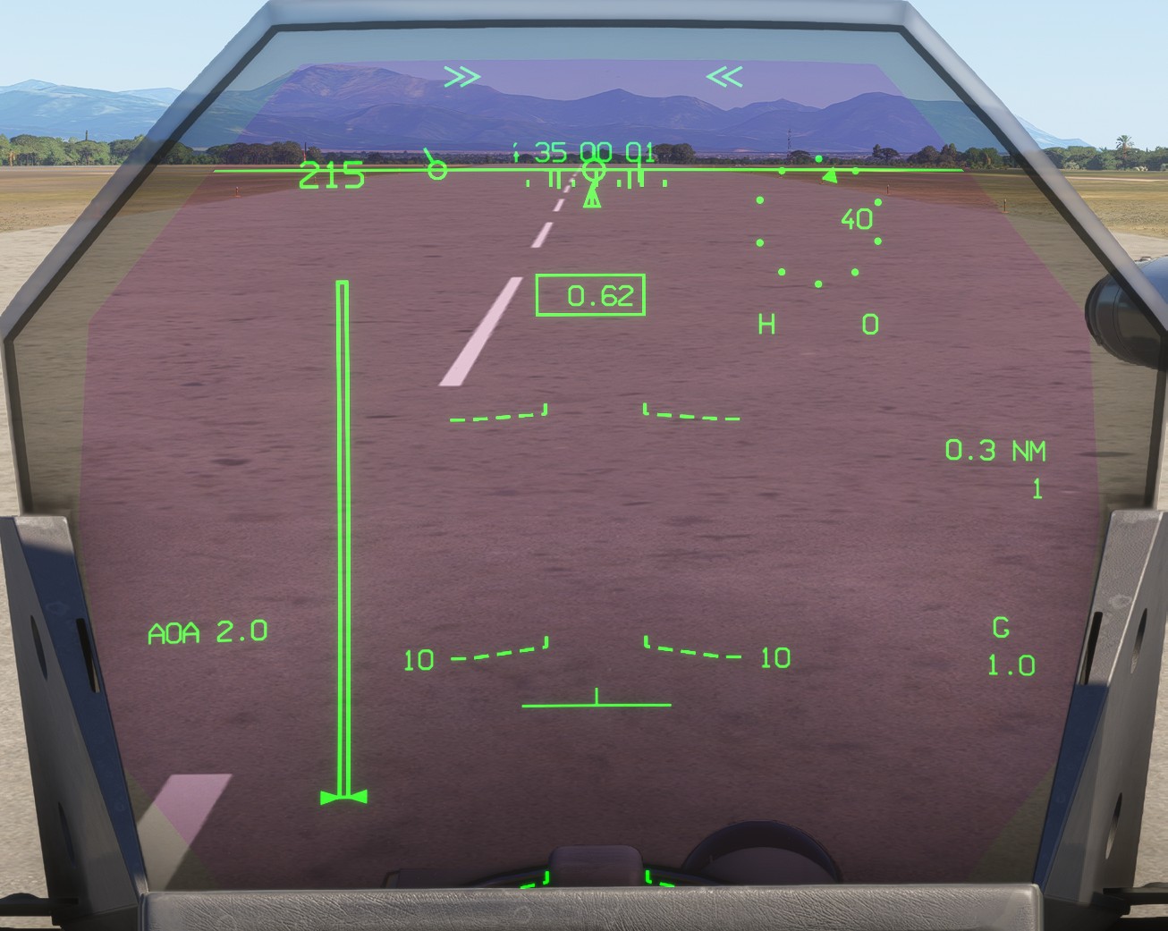
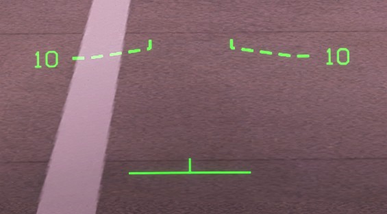
A fixed pitch reference is displayed at 13 degrees to indicate the target pitch attitude during rotation.
Longitudinal acceleration is displayed in a box near the upper centre of the HUD. The value is expressed in g and allows the pilot to monitor acceleration during the takeoff roll. For reference, in a clean configuration and at full afterburner, the displayed value may reach approximately 0.8.

A vertical bar on the left indicates the aircraft's kinetic energy during the takeoff roll.
Approach display
This display is used when APP mode is active.
Approach mode reorganises the standard symbology so that the essential information is concentrated in the lower part of the HUD, closer to the pilot's view of the runway.
The airspeed, altitude and heading indications move to the lower part of the HUD.
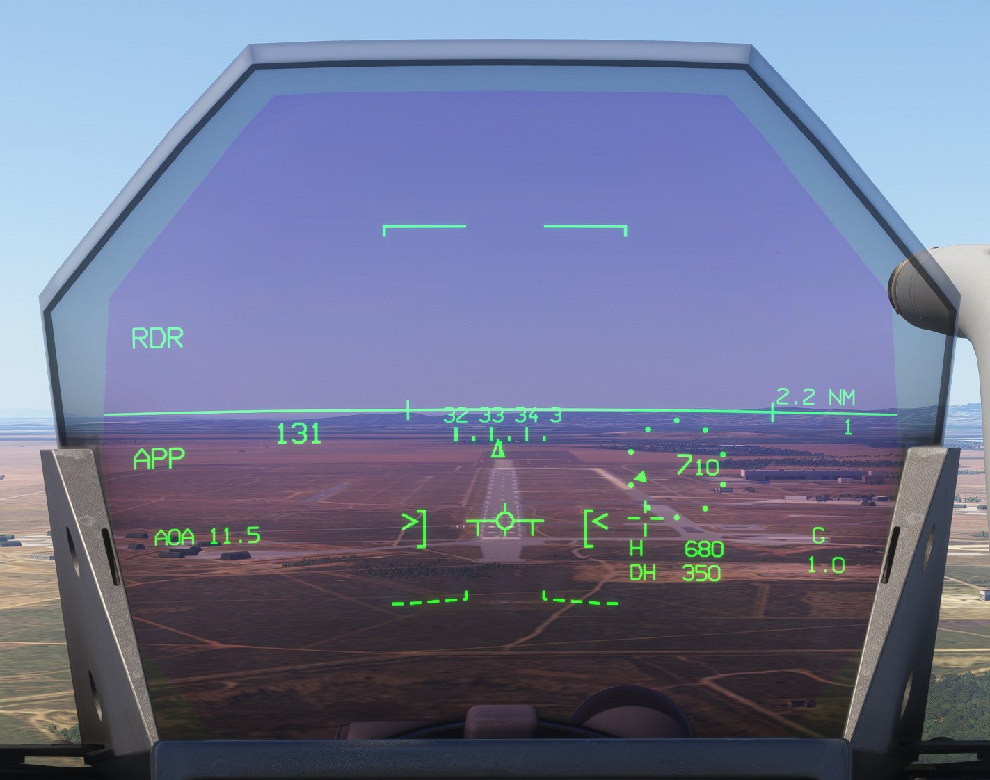
Two brackets, ] [, indicate the target angle of attack. This target uses the same setting as the autothrottle AOA hold mode.
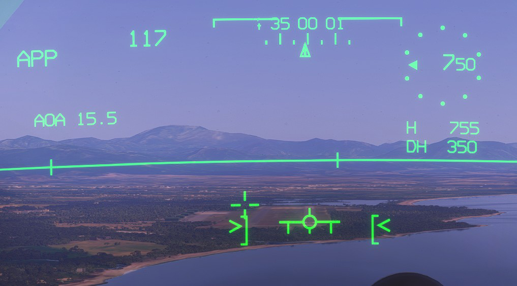
During an approach at a high angle of attack, you may need to raise the cockpit viewpoint to keep all HUD information clearly visible. Select the Landing camera from the cockpit views.
Decision height
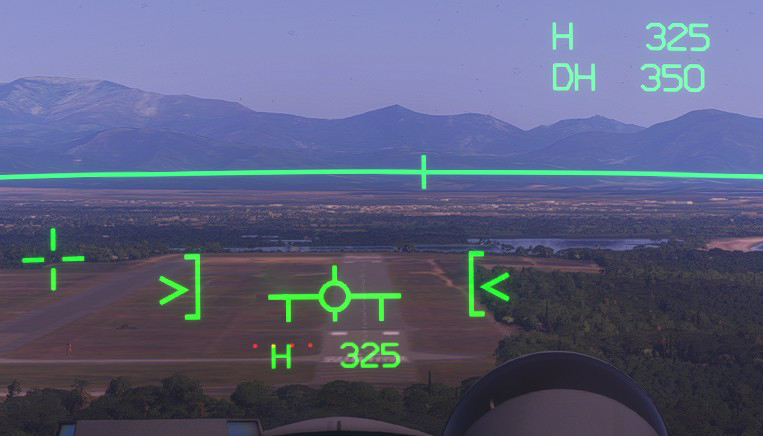
The selected decision height (DH) is displayed below the radio-height indication.
A second radio-height indication appears below the VVI and initially flashes when the aircraft descends below the selected decision height (either aircraft indicated altitude or radio height).
INS-related display
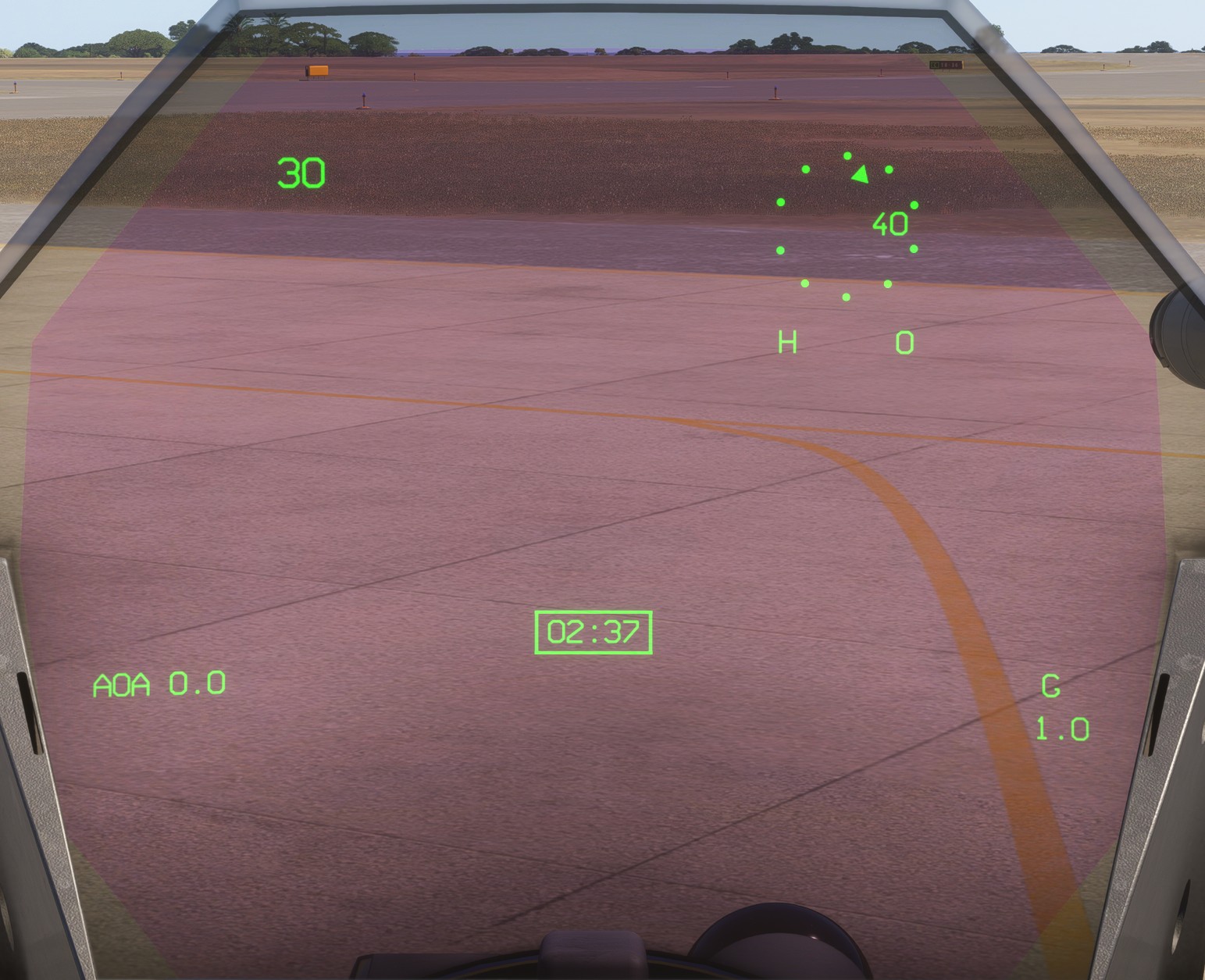
During INS alignment, the pitch and heading indications remain hidden until the system has reached a sufficient level of alignment.
A boxed countdown shows the remaining alignment time.
Navigation-related display
Primary goal
The primary goal number and its distance are displayed continuously on the right-hand side of the HUD.
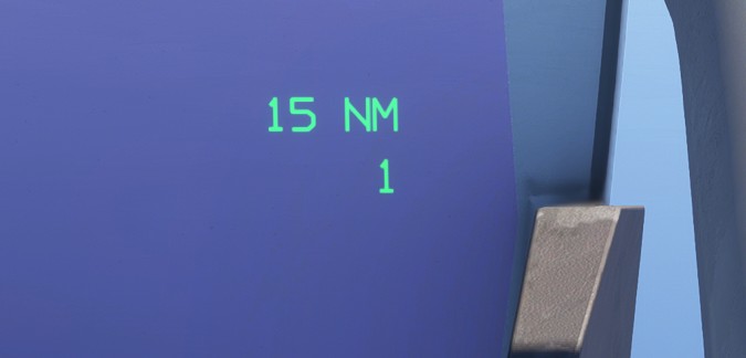
When the goal is less than 10 nm away, a cross indicates its position. The symbol is projected in three dimensions to improve spatial orientation.
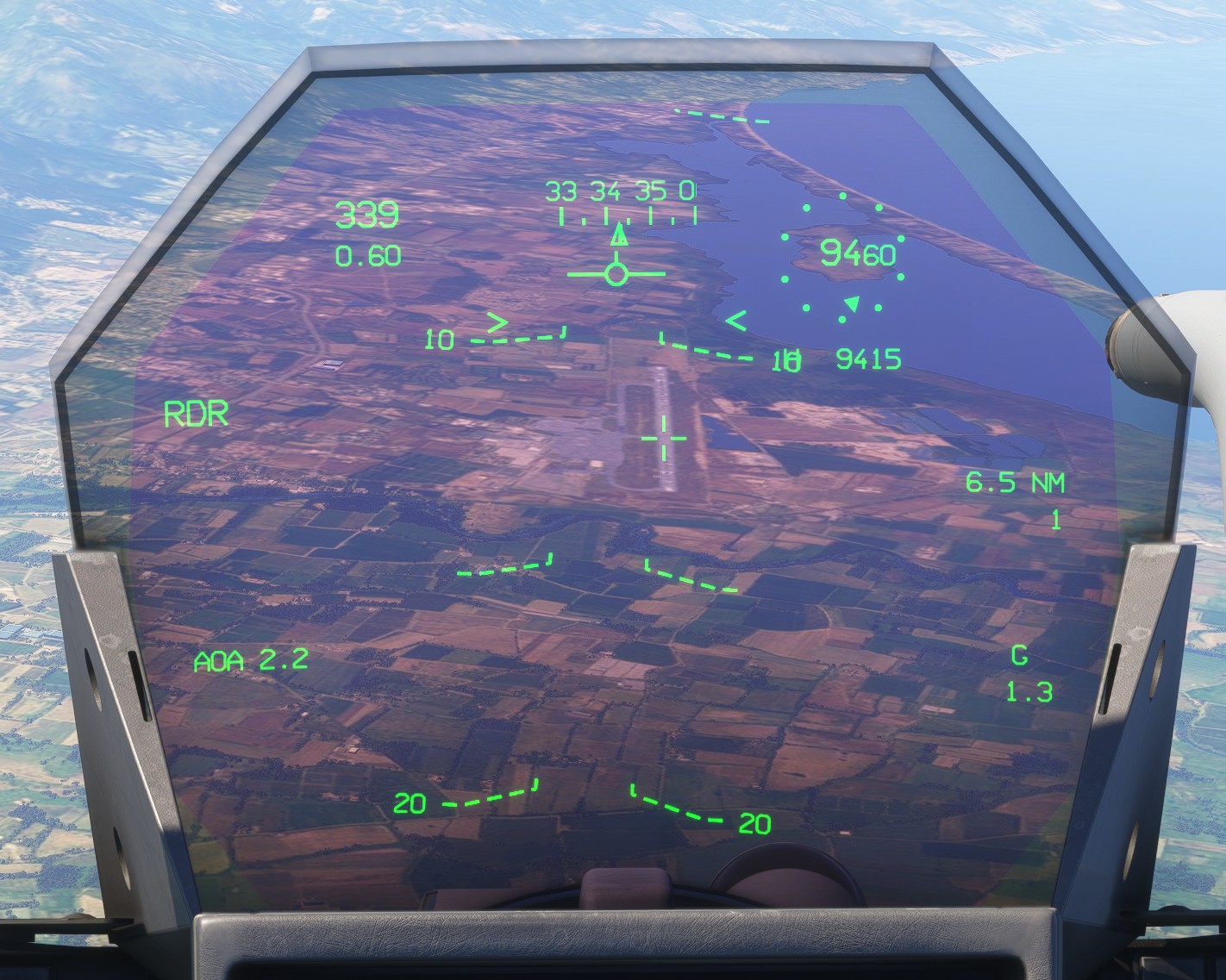
As explained in the flight plan section, some goals do not have an associated altitude constraint and are therefore projected at an altitude of zero.
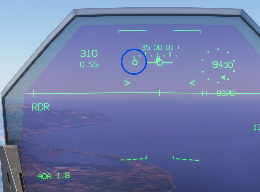
A reticle consisting of a circle and a short line indicates the direction of the goal. Unlike the projected cross, this is a two-dimensional indication.
Route deviation
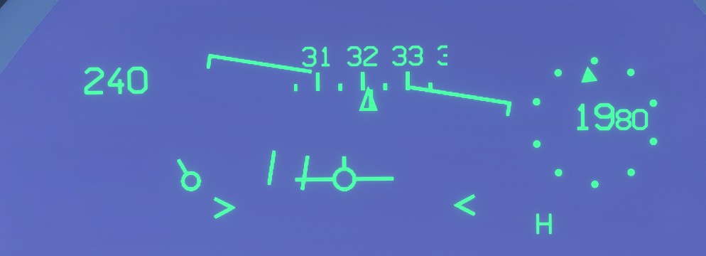
When a flight plan is active, route deviation is represented by two vertical lines forming a guidance corridor.
Placing the VVI inside this corridor guides the aircraft back towards the planned route and reduces cross-track error.
ILS
ILS guidance and synthetic runway symbology assist the pilot during approaches in reduced visibility.
A valid ILS approach must be configured for this symbology to appear.
Synthetic runway display
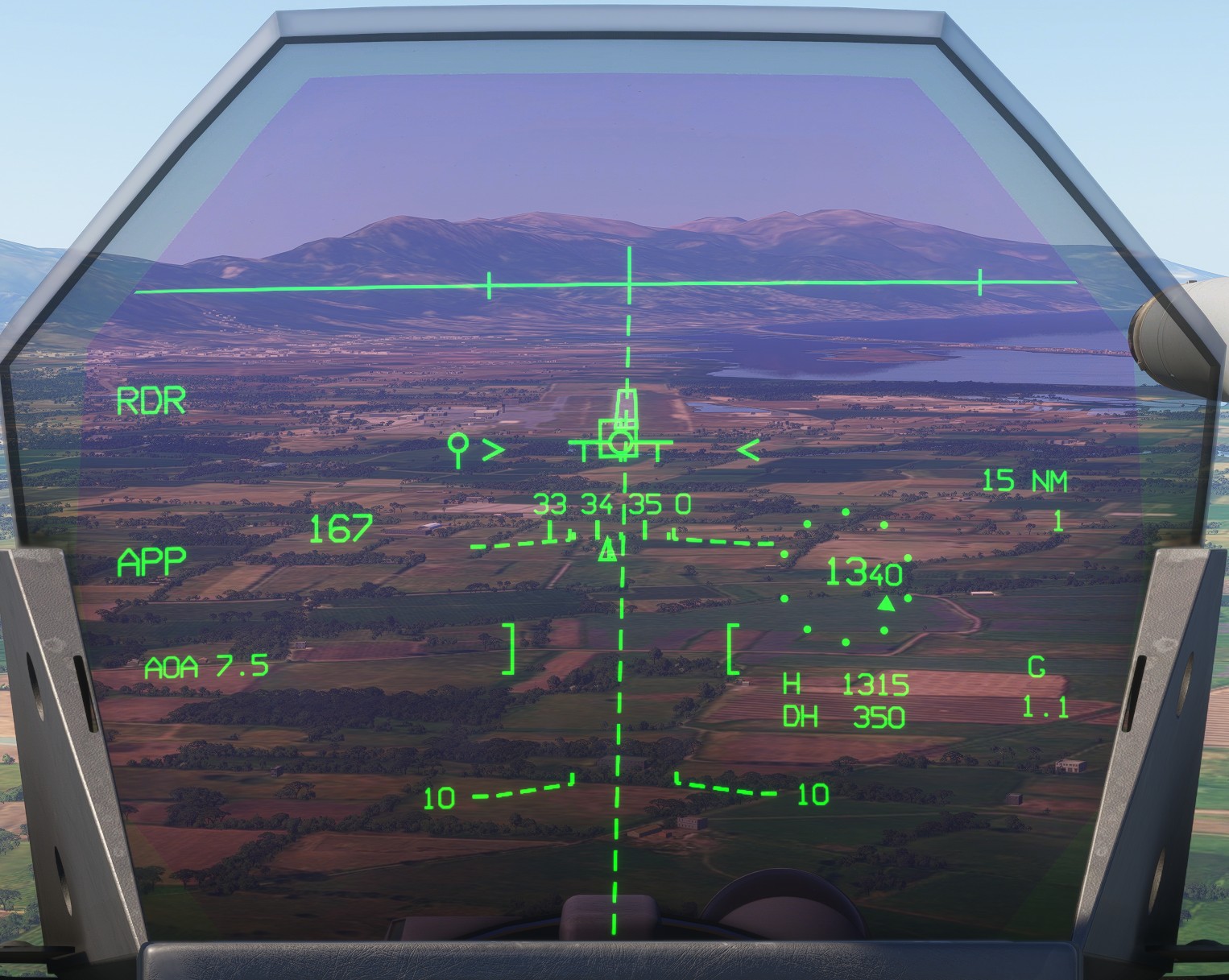
When the aircraft is within 20 nm of the airport, the approach is correctly configured and a valid ILS signal is available, the HUD projects a rectangle matching the runway dimensions onto the ground. A dashed line extends the runway centreline beyond the threshold.
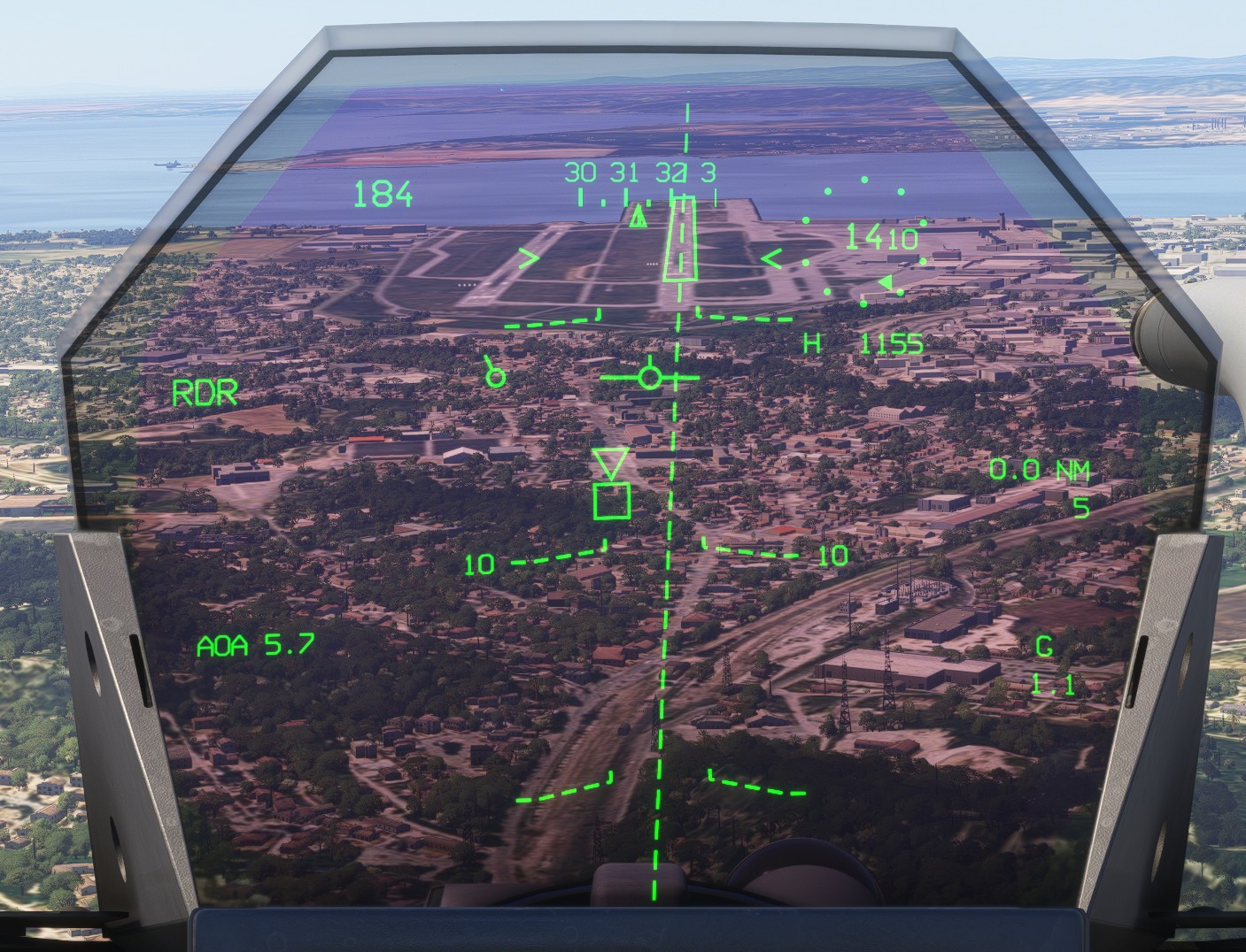
The projection disappears on short final.
The synthetic runway depends on data supplied by the simulator. For some runways, this data may be inaccurate and contain lateral or longitudinal offsets of several metres, causing the projected runway to appear displaced from the actual runway.
Guidance
When a valid localizer signal is received, a U-shaped symbol appears on the horizon line and indicates lateral deviation from the localizer course.
Steering towards this symbol helps the pilot intercept and follow the correct lateral path.
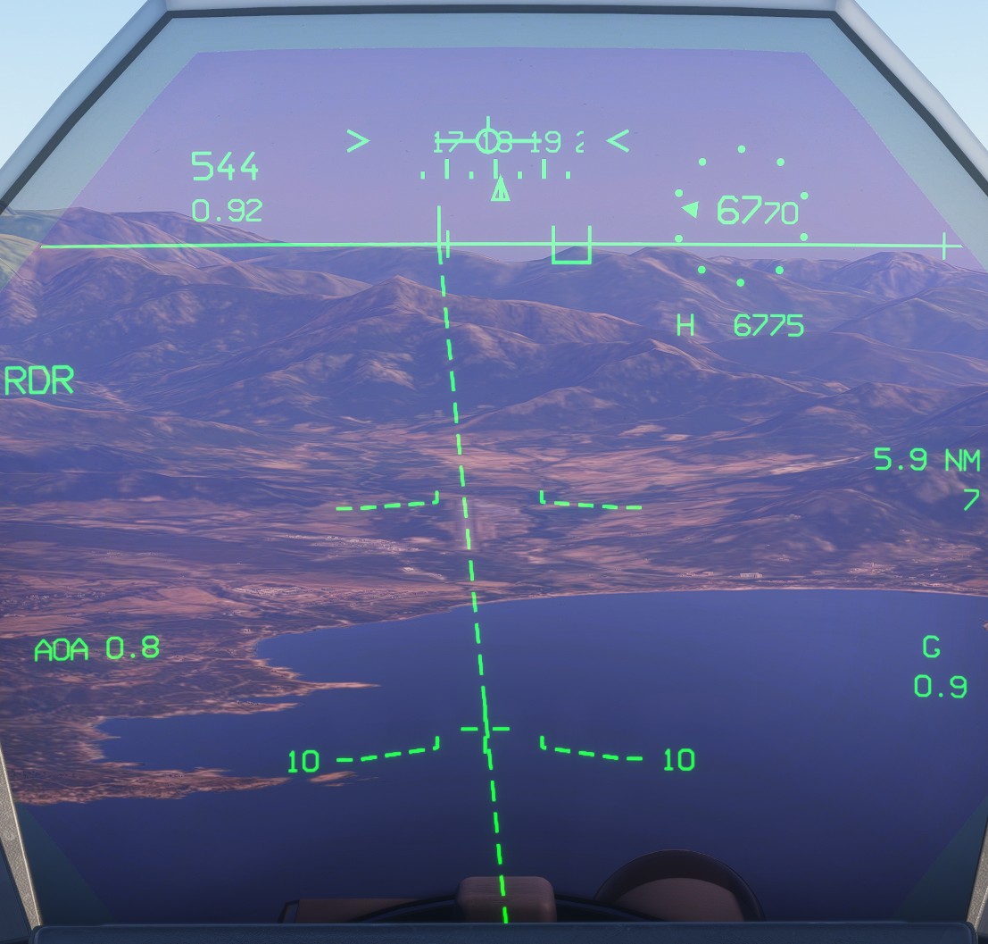
When a glideslope signal is also available, the U-shaped symbol becomes a complete square and additionally indicates vertical deviation from the glideslope. It therefore provides combined lateral and vertical guidance towards the runway.
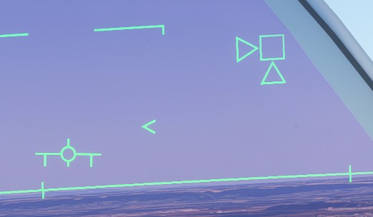
When the deviation becomes too large, an arrow indicates the direction in which the pilot must manoeuvre to recover the ILS path.
Autopilot-related display
Autopilot-specific symbology is described in greater detail in the autopilot section.
Altitude and speed target
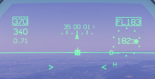
When the autopilot or autothrottle is active, the selected altitude and speed, or Mach number, are displayed inside boxes.
Flight director
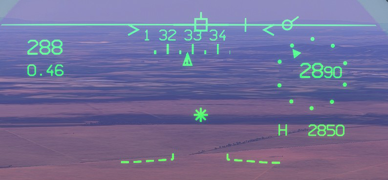
The flight director is represented by an asterisk indicating the horizontal and vertical guidance commands required to reach the selected flight parameters.
When no correction is required, the VVI and the asterisk are superimposed.
Terrain following display
When terrain following is selected, an additional symbology layer appears on the HUD.
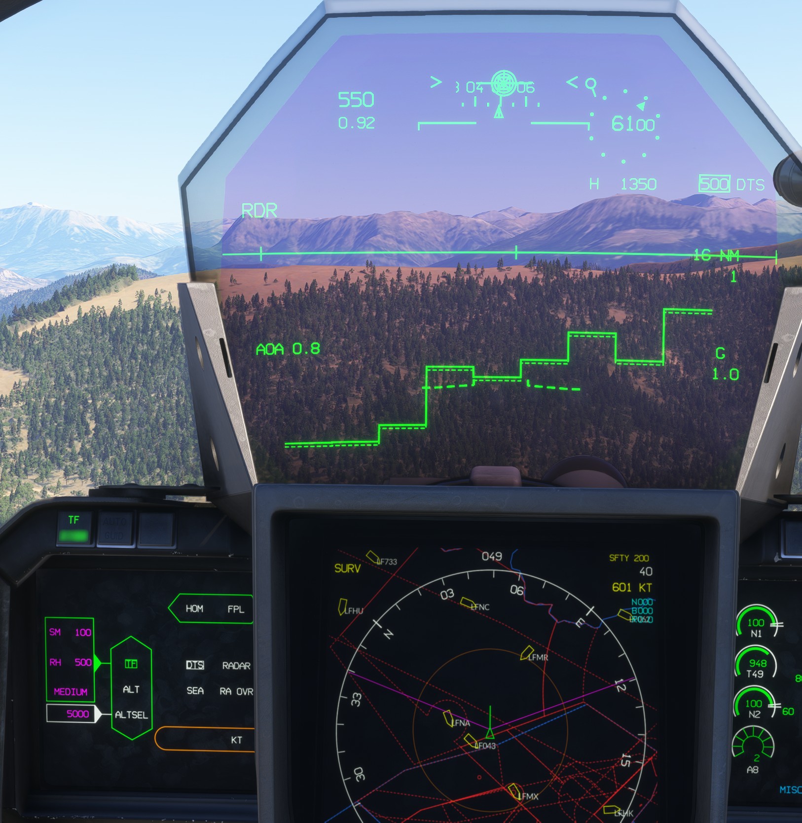
At the bottom of the HUD, a stepped pattern represents the relative elevation of the terrain ahead of the aircraft across nine scanning zones.
A raised section in the centre of the pattern indicates higher terrain directly ahead of the aircraft.
On the right, RDR or DTS indicates the data source used by the terrain-following system. The requested height (RH) is displayed immediately before it and is enclosed in a box when the autopilot is actively controlling the aircraft in TF mode.
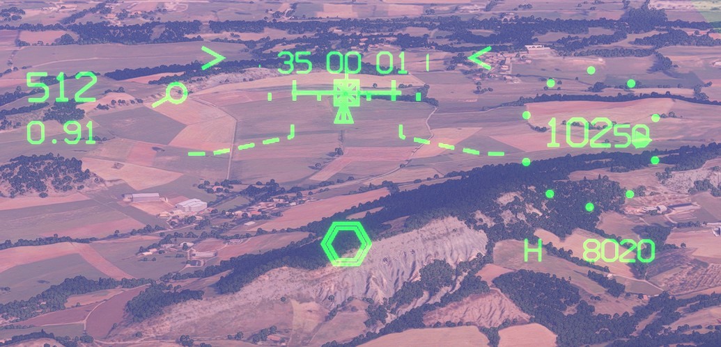
Before terrain interception, a double hexagon indicates the flight-path reference required to engage terrain following. When the VVI crosses the double hexagon, the interception begins.
Once the terrain-following path has been captured, the double hexagon changes into a double circle superimposed on the VVI, indicating that automatic terrain following is active.
Air-to-air display
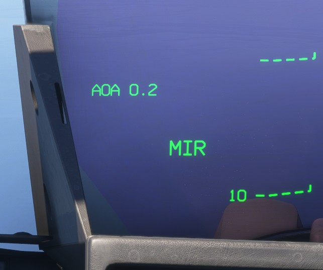
A/A mode is divided into several sub-modes: IDF, MIR, MIF and GUN.
Cycle through these modes using MG6.
The active mode is displayed in the lower-left corner of the HUD.
Target designation is performed on the center display, as explained in the weapons section.
The symbology has been deliberately simplified to remain consistent with the intended simulation scope while retaining the information required to use the system.
Common symbology
Some symbols are shared by several sub-modes.
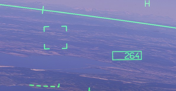
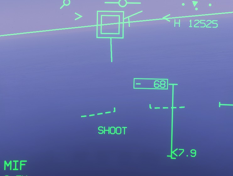
When a target is selected, its relative speed is displayed in knots inside a box on the center-right side of the HUD. A positive value indicates that the distance between the aircraft and the target is decreasing.
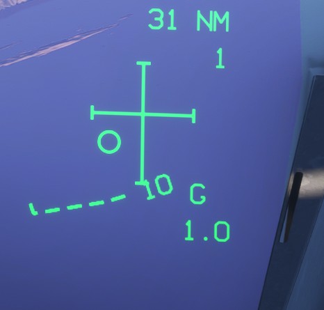
A large cross indicates the direction of the selected target relative to the aircraft. The target itself is represented by a small circle.
IDF mode
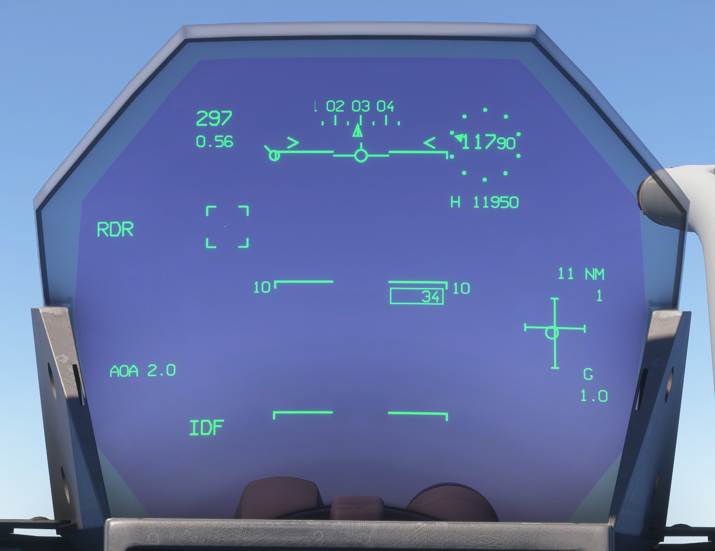
Identification mode is used to track targets without arming a weapon. It is primarily intended for air-policing and identification scenarios.
The tracked target is represented by a square.
MIR mode
This mode is used for MICA IR employment.
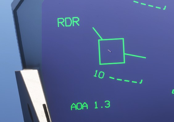
When the target is tracked by the radar, it is represented by a square with two additional lines:
- One represents the target's velocity vector.
- The other represents the line of sight between the aircraft and the target.
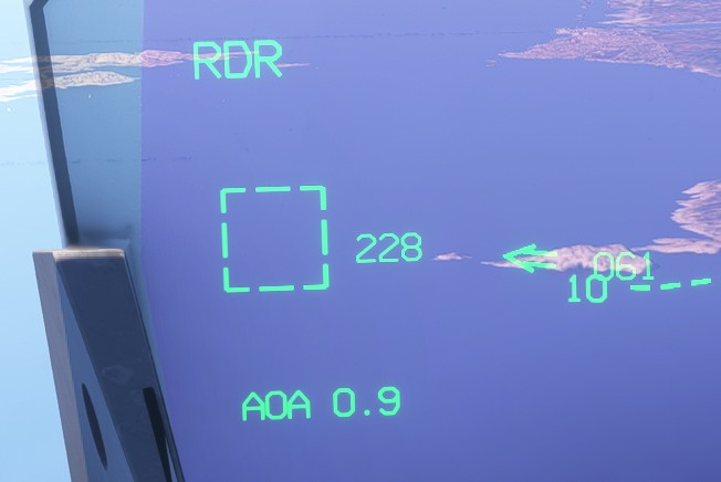
When the target is outside the HUD field of view, the square becomes dashed and the following indications are displayed:
- The target's computed track, in degrees.
- An arrow indicating the direction of the target.
- The heading difference between the aircraft and the target.
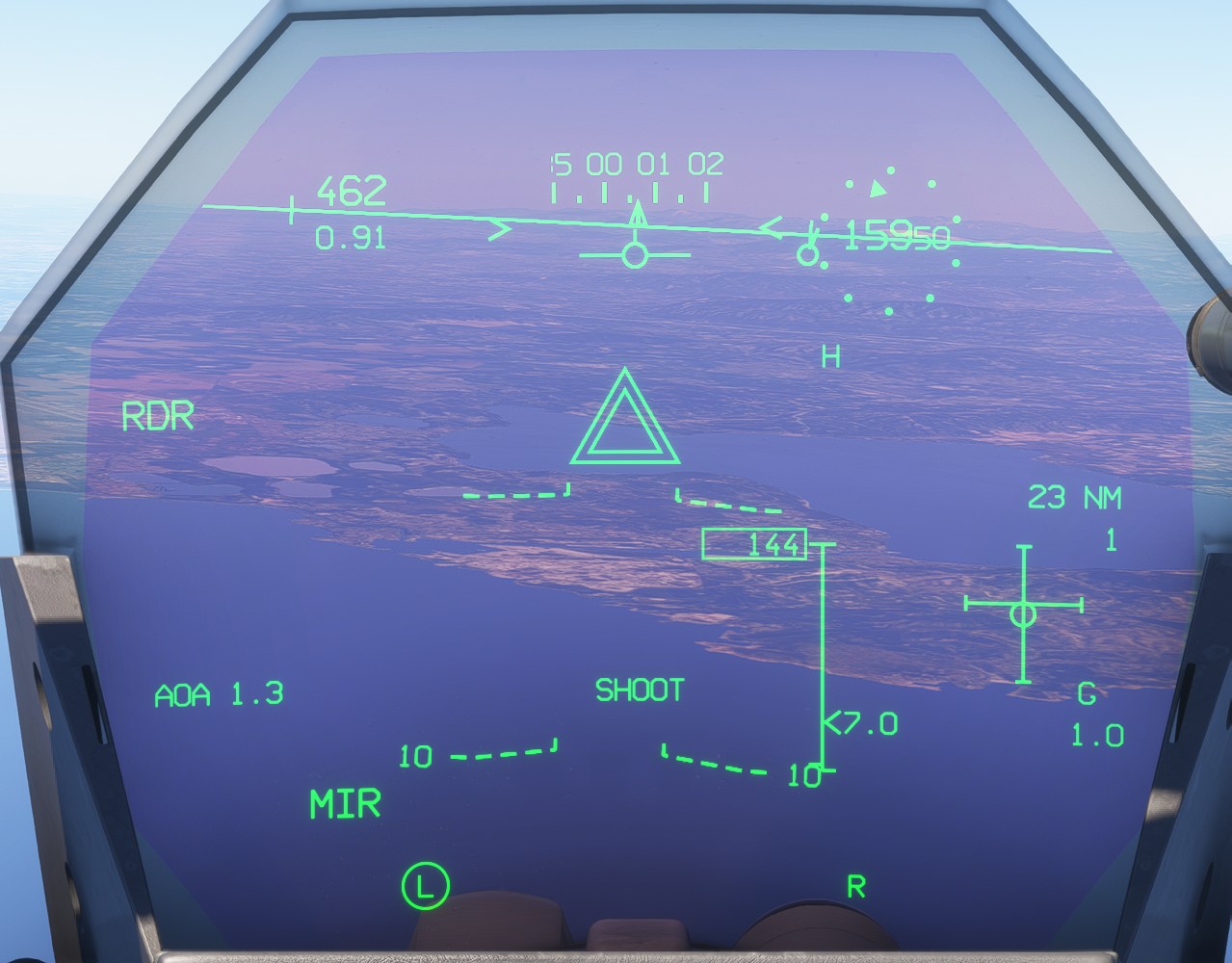
In addition to the common symbology, a range scale with a moving cursor indicates the distance to the target in nautical miles. The scale also represents the simulated weapon engagement envelope and helps determine an appropriate launch point.
At the bottom of the HUD, the letters L and R represent the two MICA IR missiles that can be carried on the wingtip stations. A circle appears around a letter when the corresponding missile is ready.
When the target is tracked by both the radar and the missile's infrared seeker, a circle appears inside the target square.
When the system determines that the target is within the simulated engagement envelope and the launch conditions are suitable, a SHOOT cue appears on the HUD.
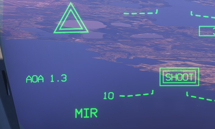
Once the missile has been fired, the SHOOT cue is enclosed by two rectangles.
MIF mode
This mode is used for radar-guided missile employment. Its symbology is similar to MIR mode, with several differences.
Each available missile is represented at the bottom of the HUD:
Erepresents an electromagnetic-guidance missile, either a MICA EM or a Meteor.Irepresents an infrared-guided MICA IR.- A small dot above the letter indicates that the missile is carried on a ventral station.
The number of available electromagnetic-guidance missiles is displayed below the MIF indication.
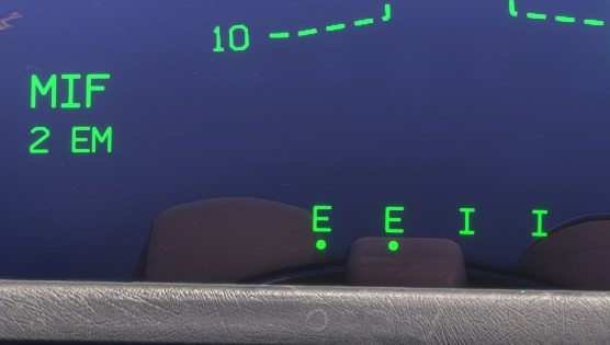
When the target is tracked by both the radar and the selected missile, it is represented by a double square.
GUN mode
The gun display adds the following elements:
-
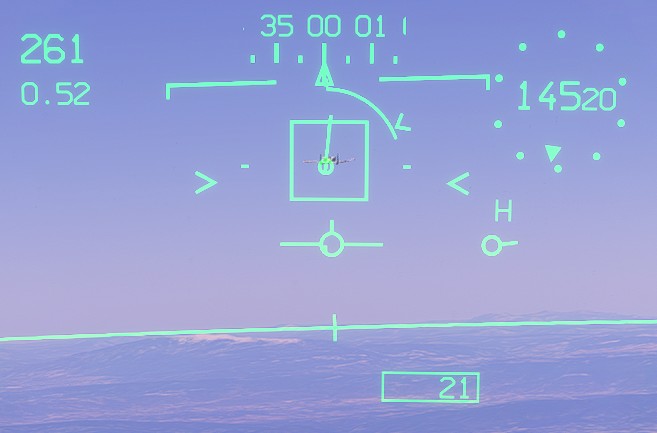
A predicted shell-trajectory line showing where rounds would travel if the gun were fired immediately.
-
When the target is less than 1 nm away, a gunsight moves along this line according to the target range. It includes:
- A target-tracking square when the target is radar-tracked.
- A range circle indicating the distance to the target, with each quarter representing 0.25 nm.
- A
>marker showing the predicted target range in five seconds. When the marker is outside the range circle, the target is moving away; when it is inside, the target is closing.
-
The remaining ammunition count, which disappears when no rounds remain.
If the predicted shell-trajectory line intersects the target, firing at that moment should result in a hit within the limits of the simulation.
Air-to-surface display
A/S mode is divided into several sub-modes: AGB, AGM and GUN.
Cycle through these modes using MG6.
The active mode is displayed in the lower-left corner of the HUD.
AGB mode
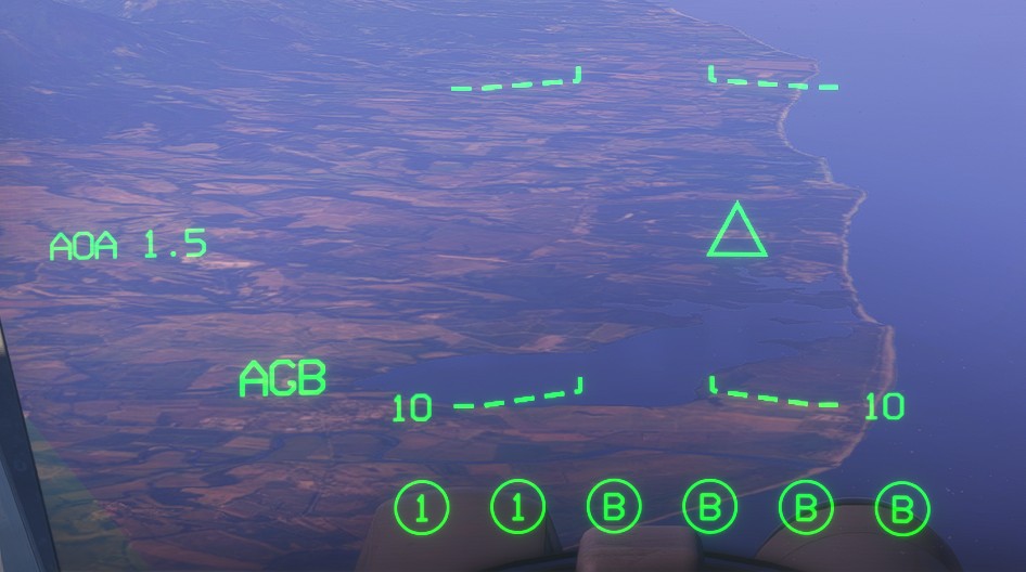
This mode is used for GBU-12 and AASM employment.
The bombs carried by the aircraft are listed at the bottom of the HUD. When a bomb is ready and a surface target has been designated, its B indication changes to 1.
The designated target is represented by a projected triangle.
AGM mode
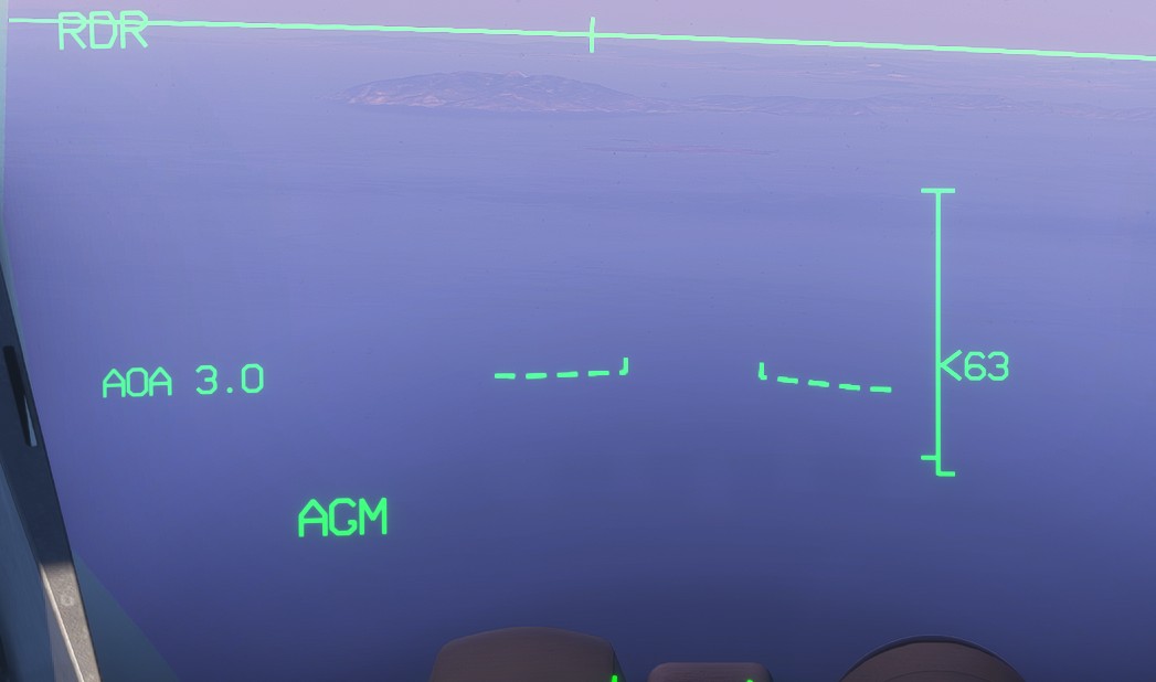
This mode is used for SCALP cruise missile employment.
Once a target has been designated, a range scale indicates the simulated optimal missile launch envelope.
GUN mode
The symbology is similar to the A/A gun display, except that no target is tracked.
The range circle indicates the calculated distance to the ground impact point.