Autopilot
The automatic flight-control system is divided into two independent parts:
-
The main autopilot, which manages vertical and lateral guidance.
-
The autothrottle, which manages aircraft speed by controlling engine thrust.
The active autopilot and autothrottle modes are displayed on the PDS2 screen.
The Rafale autopilot operates differently from the systems found in most conventional aircraft. We strongly recommend reading this section carefully before using it.
A significant amount of custom logic is used to reproduce the aircraft's specific autopilot operation. Avoid using the default MSFS bindings for individual autopilot modes, such as altitude hold, as they may interfere with this custom logic and cause unexpected behaviour.
Autopilot
The main autopilot provides several vertical and lateral guidance modes.
The available vertical modes are:
- Pitch hold, which is the default vertical mode.
- Altitude hold (
ALT). - Altitude selection (
ALTSEL). - Terrain following (
TF).
The available lateral modes are:
- Bank hold, which is the default lateral mode.
- Heading hold (
HDG). - Homing (
HOM). - Flight plan following (
FPL).
The ILS approach mode provides both vertical and lateral guidance.
The autopilot is managed from the LD AP page.

Operation
The autopilot can be engaged using the PM8 switch and disengaged using PM9.
It can also be engaged by selecting the amber vertical and lateral mode containers on the lateral display autopilot page. Both containers turn green when the autopilot is active.
The main autopilot can only be engaged when all the following conditions are met:
- The aircraft is airborne.
- The bank angle is below 50°.
- The pitch angle is below 40°.
- The spin switch is not enabled.
- The FCS is operating in digital mode.
The autopilot disconnects automatically if the aircraft returns to the ground or if the pilot makes a significant stick input. An aural warning is played when the system disconnects.
Autopilot submodes can only be selected once the main autopilot is active.
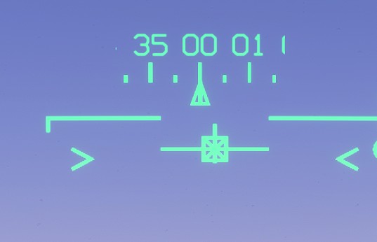
When the autopilot is engaged, the HUD vertical velocity indicator (VVI) is displayed inside a square.
Base mode
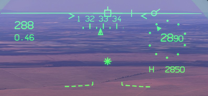
Base mode is selected by default when the autopilot is engaged. It maintains the aircraft's current pitch and bank attitude.
If the aircraft pitch is close to level when the autopilot is engaged, altitude hold is selected automatically.
If the bank angle is below 10° when the autopilot is engaged, the commanded bank angle is automatically set to zero.
The PM3/trim switch can be used at any time to adjust the commanded pitch or bank angle.
On the HUD, the flight director asterisk represents the current guidance command. When the asterisk is superimposed on the VVI, the aircraft is following the trajectory commanded by the flight director.
Altitude hold
ALT mode captures and maintains the aircraft's current altitude.
It can only be engaged when the aircraft pitch angle is below 20 degrees.
Moving the PM3/trim switch disengages ALT mode and returns the autopilot to base mode.
Once the selected altitude has been captured and is being maintained, the HUD altimeter is replaced by the target altitude displayed inside a square.
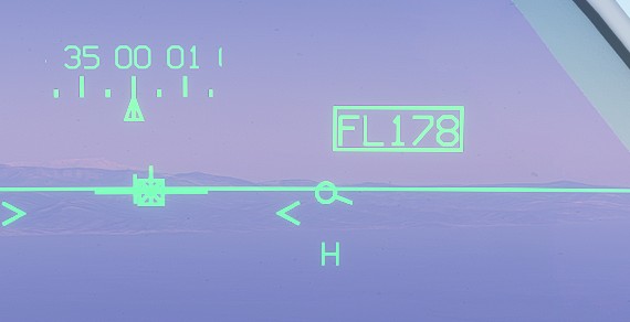
Altitudes above 10,000 ft are displayed using flight-level (FL) notation, regardless of the selected barometric setting. For example, a target altitude of 15,300 ft is displayed as FL153.
Altitude selection
ALTSEL mode is used to capture an altitude selected on the LD AP page or with the MFK.
After engaging the mode, the pilot must set the desired climb or descent attitude manually using the PM3/trim switch.
As the aircraft captures the selected altitude, the target value flashes three times on the HUD. ALTSEL then disengages automatically and ALT mode becomes active.
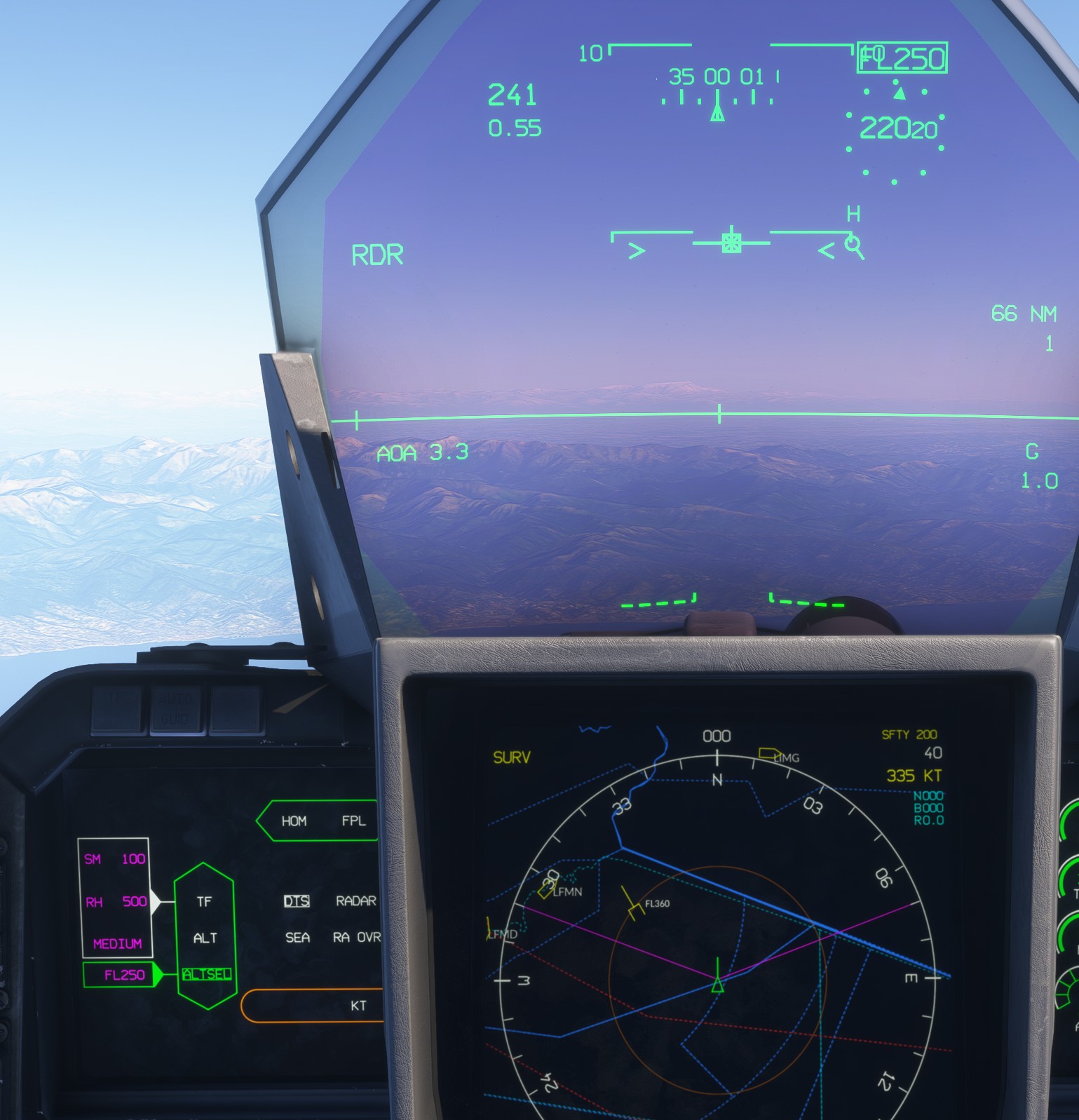
Engaging ALTSEL does not automatically initiate a climb or descent. The required pitch attitude must be commanded manually.
Heading
Heading hold mode (HDG) is entered by pressing both toe brakes while the autopilot is active. The mode initially captures the aircraft's current ground track.
HDG mode is not represented by a dedicated container on the autopilot page. Its activation is instead indicated by an arrow on the HUD and the center display.
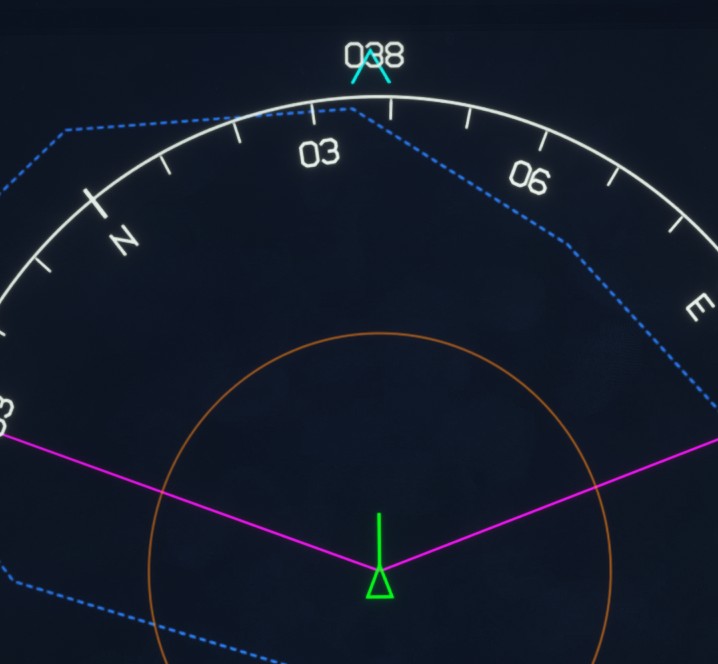
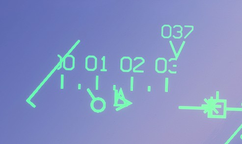
As on the real aircraft, once the mode is active, the left and right toe brakes are used to decrease or increase the selected target. Greater pedal travel produces a larger change.
This behaviour can be enabled or disabled using an EFB assistance option.
If your hardware does not support differential braking, the INCREASE HEADING BUG and DECREASE HEADING BUG bindings can be used to adjust the target instead.
The value initially captured by this mode is the aircraft's current ground track, regardless of whether the display is configured to use magnetic or true reference.
Moving the PM3/trim switch disengages heading hold and returns the lateral autopilot to base mode.
Flight plan
Flight plan mode (FPL) automatically follows the active flight plan laterally. It does not manage the aircraft's altitude.
The system automatically adjusts the aircraft's bank angle to remain on the planned route.
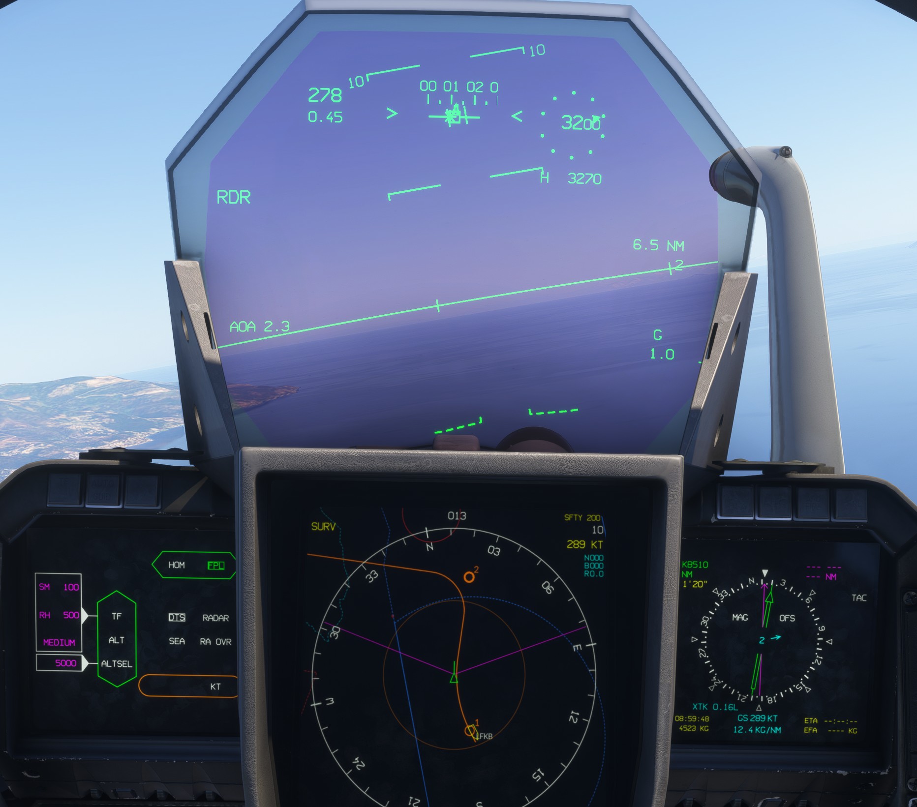
Aircraft speed must be monitored carefully while using FPL mode. At excessive speeds, the autopilot may be unable to follow tight turns, particularly during departure or arrival procedures.
Homing
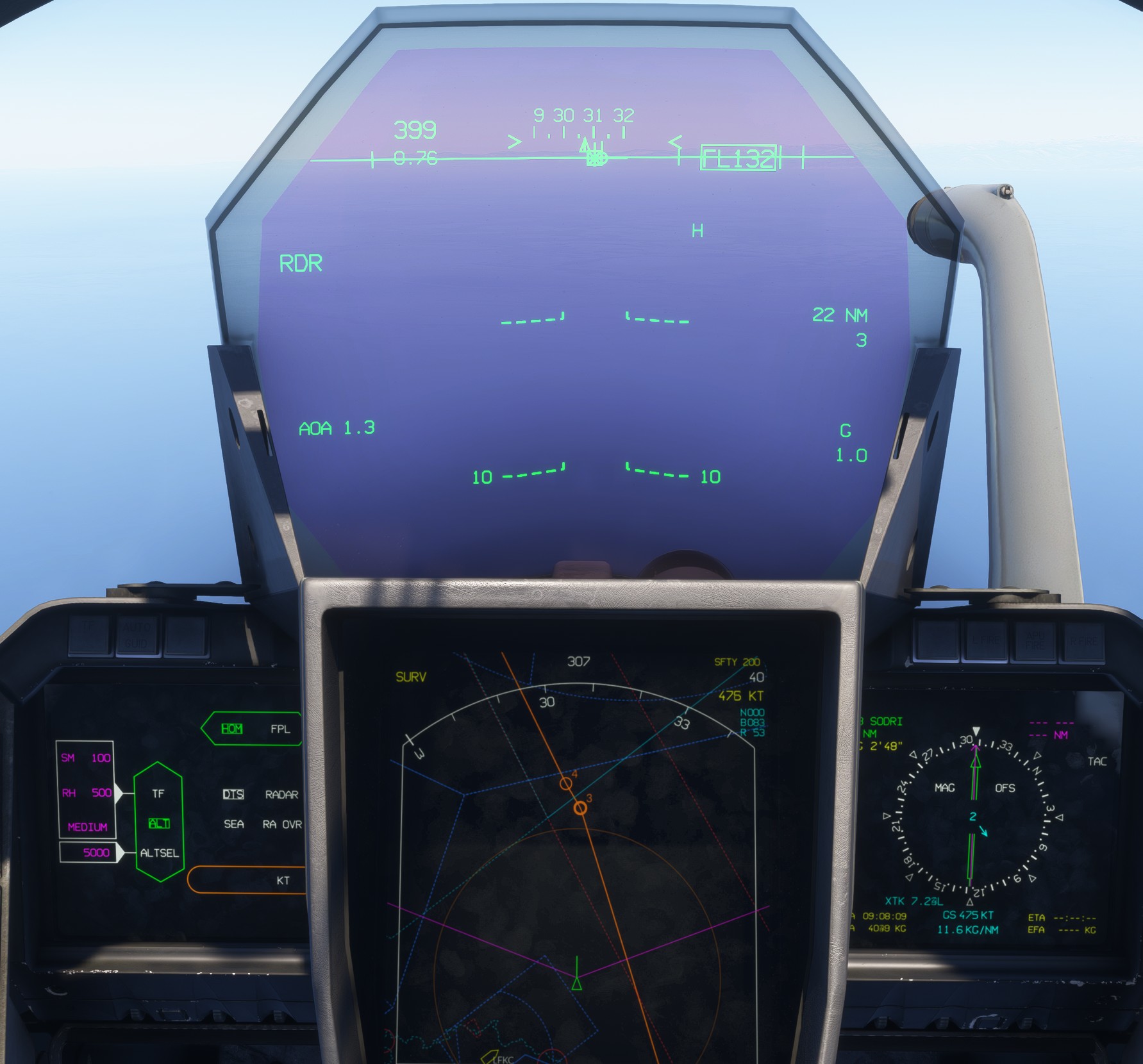
In homing mode (HOM), the aircraft flies directly towards the primary goal without attempting to intercept or remain on the planned route.
This is equivalent to flying directly towards each active waypoint in a straight line.
ILS
When a valid ILS approach is configured, the autopilot can provide automatic localizer and glideslope guidance. This mode is particularly useful in low-visibility conditions.
When valid localizer and glideslope signals are received, the LD HSI page displays the corresponding lateral and vertical deviations.
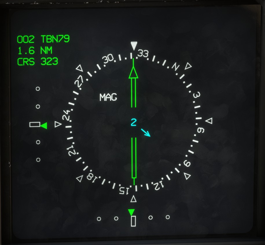
Once APP primary mode is active, an ILS button becomes available on the autopilot page. Select it to arm the automatic approach mode.
The button and its label turn green once both the localizer and glideslope have been captured. The AUTO GUID indicator also illuminates.
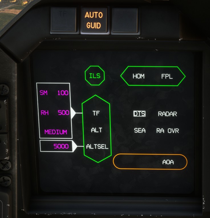
Before engaging the approach mode, ensure that the aircraft is stabilized at an appropriate approach speed and is reasonably aligned with both the localizer and glideslope. Otherwise, the autopilot may struggle to establish the correct trajectory.
If the ILS box is not displayed on the HUD and no ILS information appears on the LD HSI page, the ILS approach may not be configured correctly in LD APP, or the aircraft may not yet be within the area where the ILS signals can be received. In this situation, selecting ILS on the autopilot page has no effect.
The current automatic approach mode relies on the default MSFS autopilot, which may produce oscillations at the relatively high angles of attack used during approach. Improvements are planned in future updates.
Terrain following
Terrain following (TF) is a specialised guidance mode designed to reduce pilot workload during low-level flight, particularly in low-visibility conditions.
In our implementation, the system samples the terrain ahead of the aircraft, builds a terrain profile, generates a suitable vertical flight path and commands the flight-control system to follow it. This broadly reproduces the operating principle of a terrain-following system within the limitations of Microsoft Flight Simulator.
The terrain-following system can use two selectable terrain-data sources:
RADAR: represents terrain data obtained through active radar scanning.DTS: represents topographic data stored in the aircraft's database, allowingTFguidance to be used without radar emissions.
In our implementation, both options use the same underlying simulator terrain data.
TF can be selected on the LD AP page without engaging the autopilot. In this configuration, the calculated terrain data is displayed on the HUD and can be followed manually.
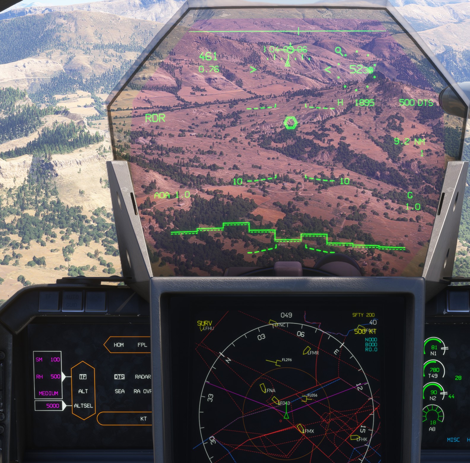
Terrain following is implemented natively in this add-on and is designed to remain usable across a wide range of environments. However, edge cases may still occur because of terrain-data resolution and simulator limitations. The system may be refined in future updates.
Settings
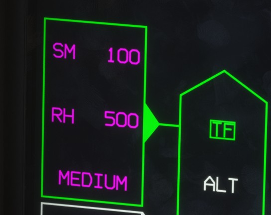
Terrain-following behaviour is configured using three settings:
-
Requested height (
RH): the desired clearance above the terrain. It can be set between 200 and 2,000 ft. -
Safety margin (
SM): an additional clearance added to the requested height to account for obstacles such as power lines and other narrow vertical structures that may not be represented reliably in the terrain data. It can be set between 0 and 1,000 ft. -
Ride law: controls how aggressively the system reacts to changes in the terrain profile. Three settings are available:
-
SOFT: reduced responsiveness, suitable for smooth terrain or greater clearances. -
MEDIUM: balanced responsiveness for most situations. -
HARD: increased responsiveness for steep terrain or low requested heights, resulting in higher-G manoeuvres.
-
Operation
TF can be selected from the LD AP page or by clicking the terrain-following indicator.
Once armed, the mode can activate only when all the following conditions are met:
- Indicated airspeed is between 400 and 600 kts.
- Bank angle is below 60°.
- Nose-down pitch angle is below 50°.
While TF is armed but not yet active, the HUD displays a double hexagon representing the interception cue. When the VVI crosses this cue, TF becomes active and the symbol changes to a double circle around the VVI.
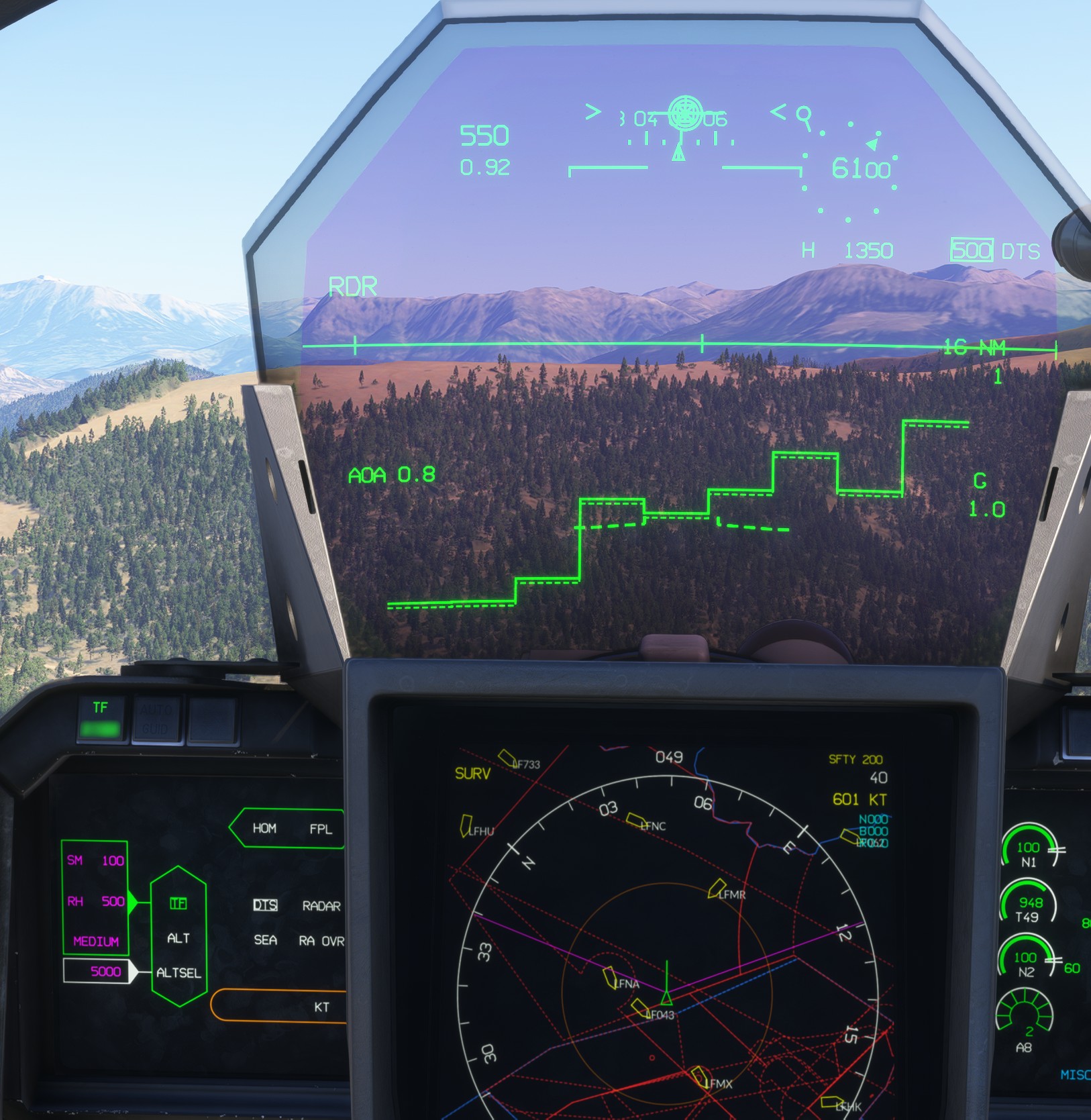
The commanded clearance is not calculated from a single terrain point. The system analyses several terrain zones ahead of the aircraft, gives greater weight to the nearest terrain and increases its margin when terrain variation or bank angle becomes greater.
Over particularly uneven terrain, the aircraft may not maintain the exact requested height at all times.
Terrain following controls only the vertical component of the flight. Lateral modes such as bank or heading hold, HOM and FPL can therefore remain active at the same time.
When aircraft speed is approaching envelope limits (400-600 kts) while terrain following is active, an alert is displated on the HUD.
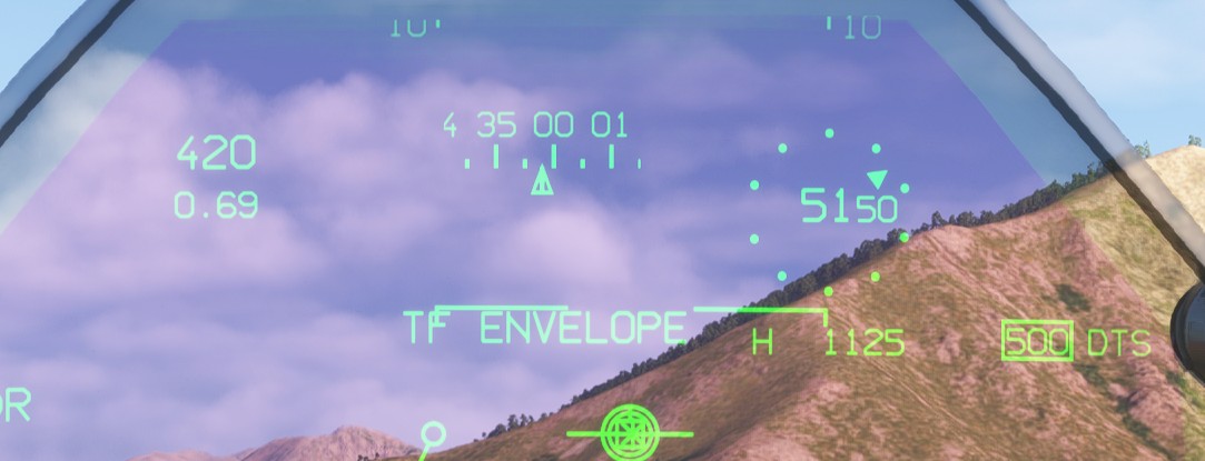
If any of the terrain following activation conditions are no longer met, the mode disengages immediately.
Autothrottle
The autothrottle operates independently from the main autopilot.
It controls engine thrust within the dry-thrust range only, from idle to maximum dry thrust.
Only engines whose AEC is set to NORM are controlled by the autothrottle.
Speed hold
A selected speed can be maintained using either of the following modes:
KT: maintains a selected indicated airspeed.M: maintains a selected Mach number.
The pilot can switch freely between KT and M modes.
Above 20,000 ft, M mode is selected by default.
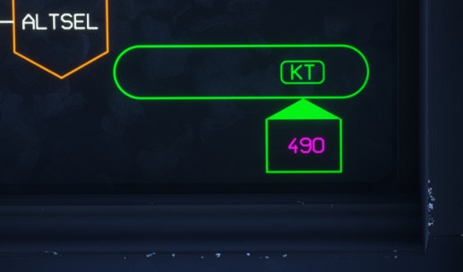
When the autothrottle is active, the selected speed is displayed inside a box on the HUD.
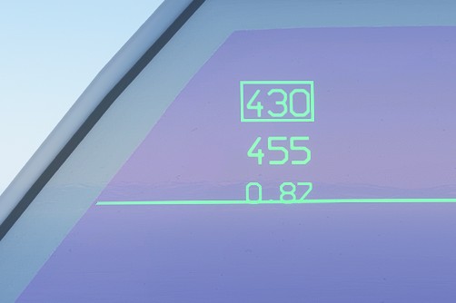
When the aircraft is within ±10 kts or ±0.05 Mach of the selected target, the target indication merges with the current speed indication.
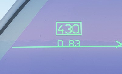
If the aircraft speed subsequently moves outside this tolerance, the target indication flashes three times.
Angle of attack hold
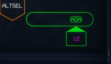
AOA mode maintains a selected angle of attack instead of a speed target.
This mode is primarily intended for approach operations. When the landing gear is extended, the autothrottle automatically selects AOA mode.
The default target angle of attack is 16°, which is the usual approach angle, but it can be adjusted as required between 10° and 20°.
The target angle of attack is displayed on the HUD above the indicated airspeed.
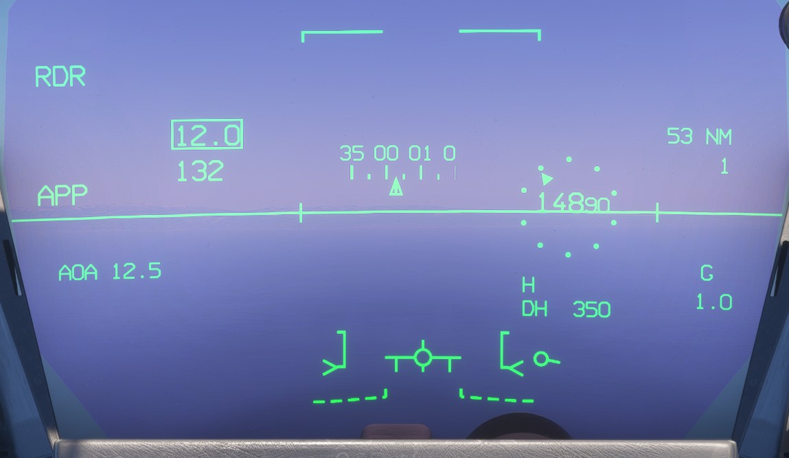
This mode is typically used at low speeds and high angles of attack. As a result, the system may need to make significant throttle adjustments to maintain the target angle of attack. These power changes can prompt the flight control system to make corresponding pitch corrections, which may result in noticeable oscillations and require regular stick inputs from the pilot to damp them out.
Operation
The autothrottle can be toggled by selecting its amber container on the LD AP page or by using MG8 on the throttle.
When KT or M mode is first selected, the aircraft's current speed is used as the initial target. The target can then be adjusted from the LD AP page using the value adjustment knob.
Selecting KT or M switches between the two speed-reference modes.
When the landing gear is extended, only AOA mode is available.
The autothrottle disengages automatically when any of the following conditions occur:
- The aircraft is on the ground.
- The throttle reaches either physical stop, at idle or full power.
- The spin switch is enabled.
- The FCS enters analogue mode.
An aural warning is played when the autothrottle disconnects.