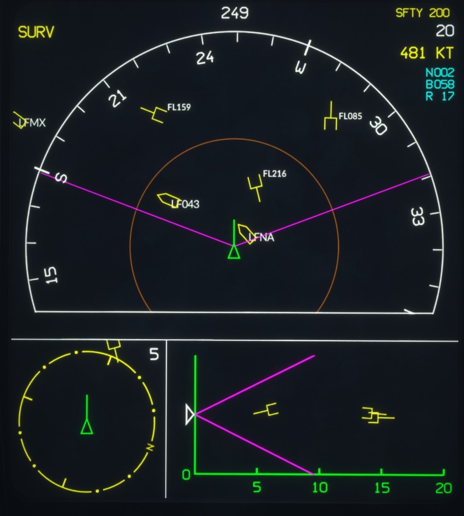
Head center display
Description
The center display is positioned directly below the HUD and close to the pilot's normal line of sight.
It is built around a map that presents navigation data and the tactical situation.
Its brightness is adjusted using the HCD Brightness Knob.
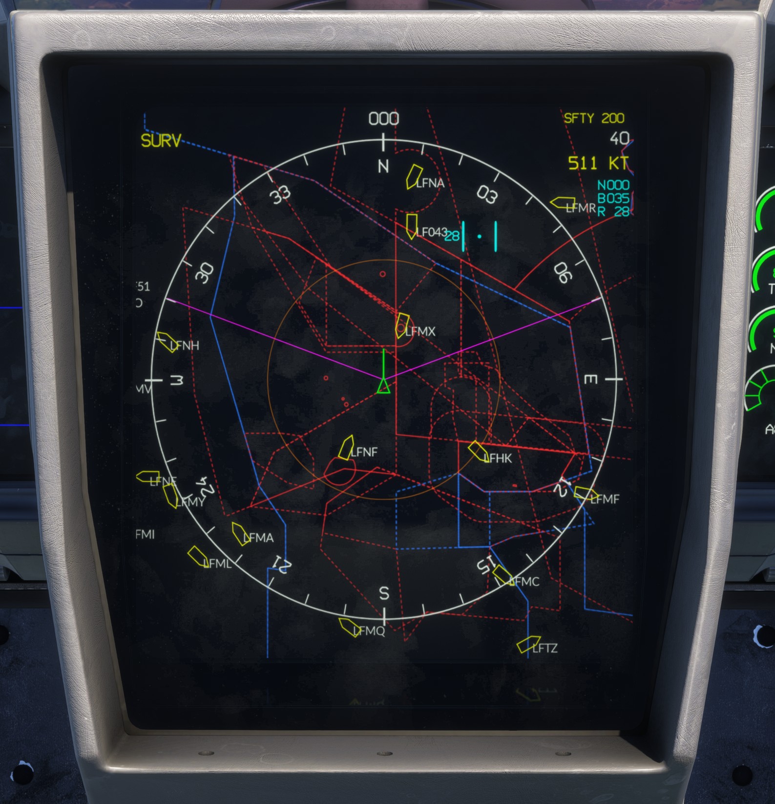
The upper-right corner displays the current safety height, the selected map range in nautical miles and the aircraft's ground speed.
Own aircraft
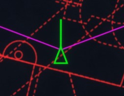
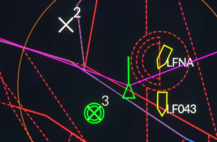
The aircraft is represented by a green triangle with a line indicating its current direction of travel.
The length of the line varies according to the aircraft's ground speed.
Compass
The display is surrounded by a compass rose graduated every 10 degrees and labelled with the four cardinal directions (N, E, S and W).
The rose rotates according to the aircraft heading, which may be magnetic or true depending on the LD HSI setting. The current heading value is displayed above the rose.
The distance between the center of the display and the compass rose corresponds to the selected range shown in the upper-right corner. The available range settings are 2, 5, 10, 20, 40, 60, 80 and 120 nm. The thin brown circle represents half of the selected range.
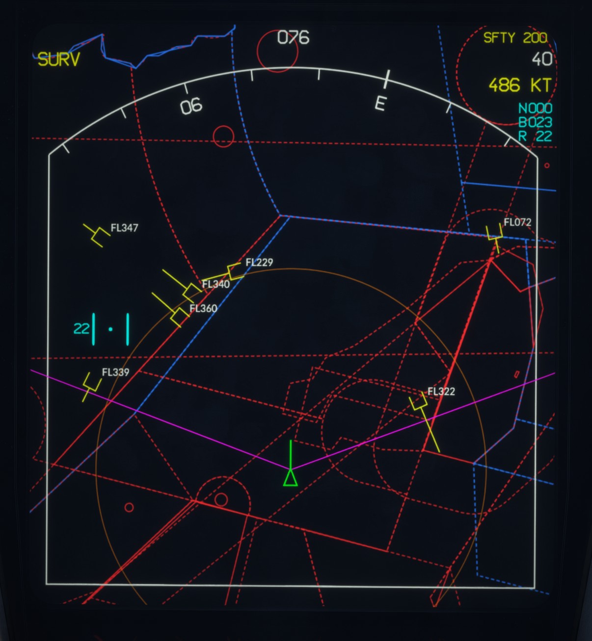
The appearance and position of the compass rose vary depending on whether the centered view mode is active.
Map
Four different map backgrounds are available. Airspace zones can be superimposed on any of them.
The default background is entirely black and does not display any topographic information.
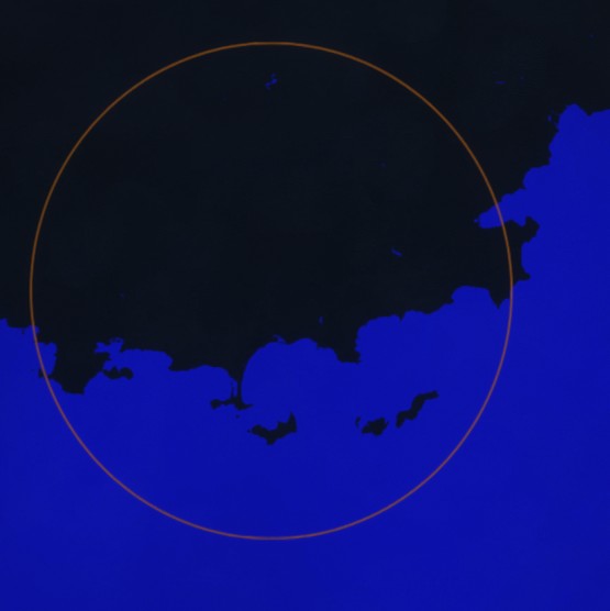
The second background is black, with bodies of water shown in blue.
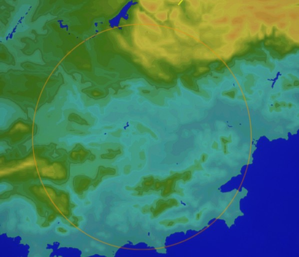
The third background is a topographic map that uses colour variations to represent terrain elevation.
A fourth option is available specifically for metropolitan France: the DIRCAM CAM chart, which is used for military air traffic circulation.
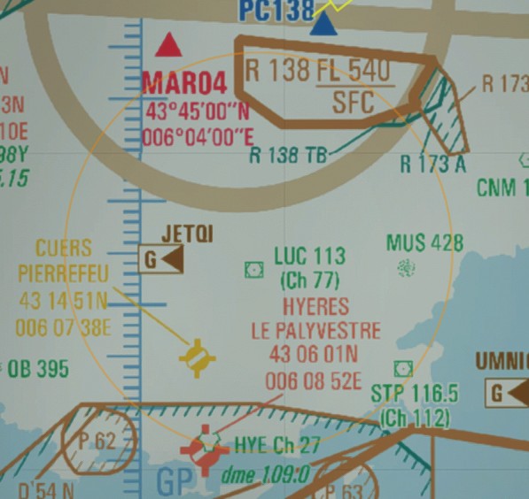
The military CAM map (France) integrated in the avionics is courtesy of DIRCAM (Direction de la circulation aérienne militaire) and is used with authorization.
Map opacity can be adjusted using the HCD Map Opacity Knob.
Navigation data
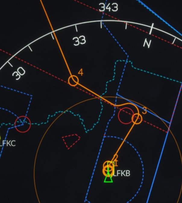
Airports with paved runways are displayed on the HCD. A yellow symbol represents the orientation of the longest runway.
The flight plan is represented by an orange line, with each waypoint shown as a circle and labelled with its corresponding database number. The primary goal, which is the active waypoint, is represented by a thicker circle.
Marker goals are represented by a cross together with their database number. They are created at the current HCD cursor position using MGP4.
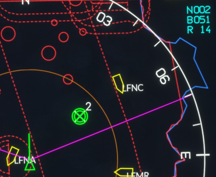
The active bullseye is represented by two concentric green circles with a cross at the center.
Traffic
As explained in the radar section, traffic detected by the radar is displayed on the HCD together with its calculated altitude.
Traffic callsigns can also be displayed as an option.

Settings
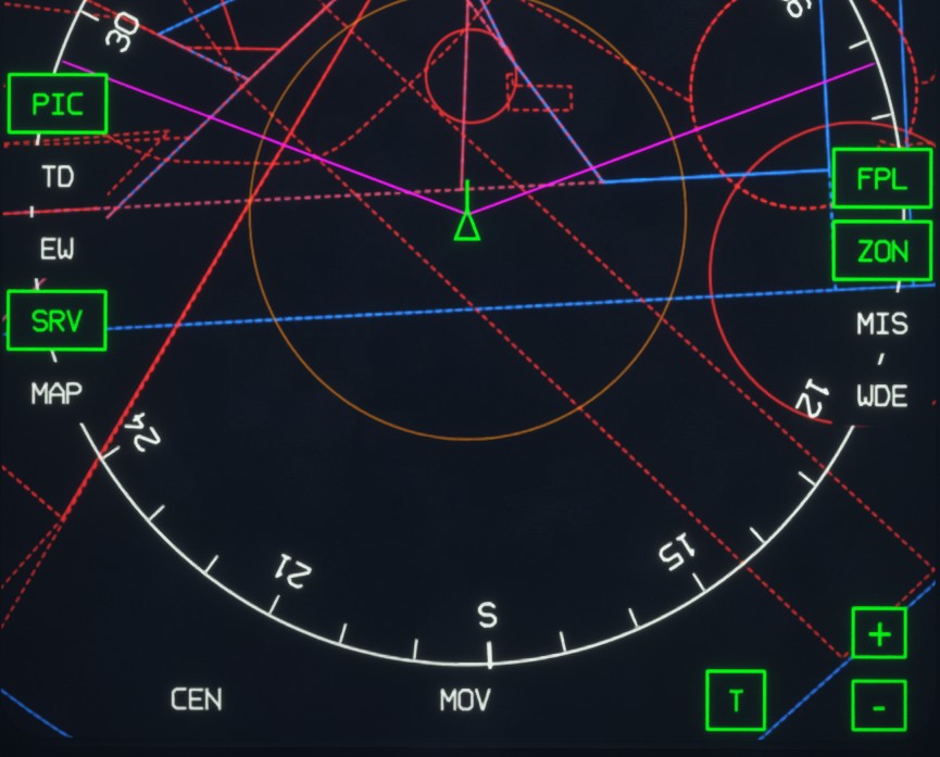
When the pointer is moved over the display, several buttons appear and provide access to the display settings.
Some buttons have active and inactive states. Active buttons are outlined in green.
-
PIC: toggles the display of callsigns above traffic symbols. -
TD: activates target designation mode. -
SRV: toggles surveillance mode and the display of detected traffic. -
MAP: cycles through the available map backgrounds. -
FPL: toggles the flight plan display. -
ZON: toggles the display of airspace zones. -
CEN: toggles the centered view mode. -
MOV: activates moving-map mode. -
T: toggles between track-up and north-up orientation. -
+/-: zooms the map in or out. This provides the same function as MGP3.
The remaining buttons are not functional in the current implementation.
Declutter
Pressing the button located below the HCD declutters the display by hiding airport symbols.

Cursor
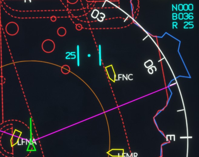
Clicking on the map places a cursor represented by a blue dot and two blue lines.
The cursor is used to designate elements on the display.
The distance from the aircraft to the cursor is shown in nautical miles to the left of the cursor.
The upper-right corner of the display shows:
B: bearing from the aircraft to the cursor.R: range from the aircraft to the cursor.
When a bullseye is active, the information box in the upper-right corner displays:
N: database number of the goal used as the bullseye.B: bearing from the aircraft to the bullseye.R: range from the aircraft to the bullseye.
A2D view
The LD DAS page allows two additional views to be displayed at the bottom of the screen:
-
The expanded view, which provides a magnified view centered on the aircraft.
-
The
A2Dview, which displays the vertical tactical situation. It shows radar-detected traffic and their vertical movement using the same range scale as the main map. The radar coverage limits are represented by magenta lines.