HYD
Description
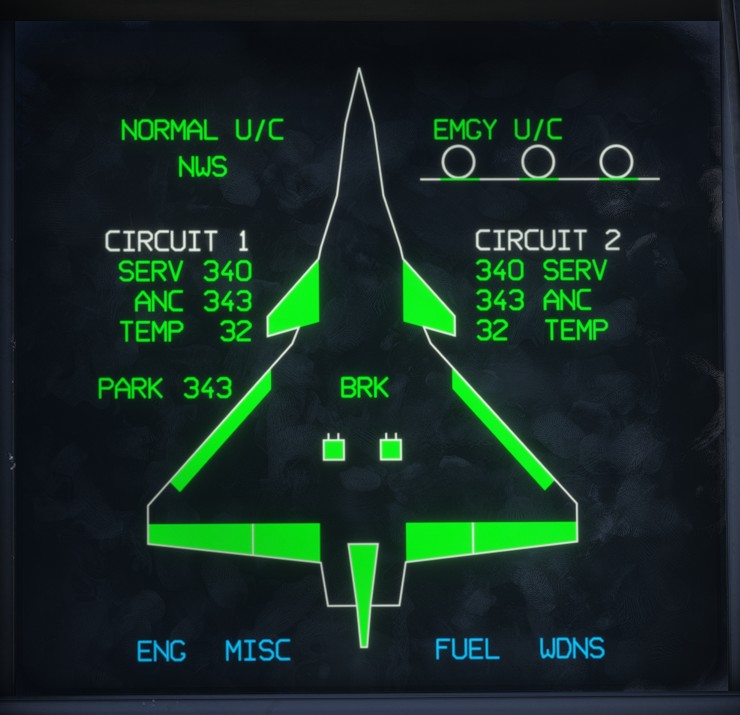
The hydraulic page provides a synoptic view of the hydraulic system, represented over a top view of the aircraft.
To access it, move the RLD Page Selection Switch to the FUEL position, then select the HYDR page.
Shortcuts at the bottom of the page provide access to the MISC, ENG, FUEL and WDNS pages.
The hydraulic system itself is described in the hydraulic system section.
Circuits
The two main hydraulic circuits are displayed as CIRCUIT 1 and CIRCUIT 2. The following information is shown for each circuit:
SERV: servo pressure, in bar.ANC: accumulator pressure, in bar.TEMP: hydraulic fluid temperature, in degrees Celsius.
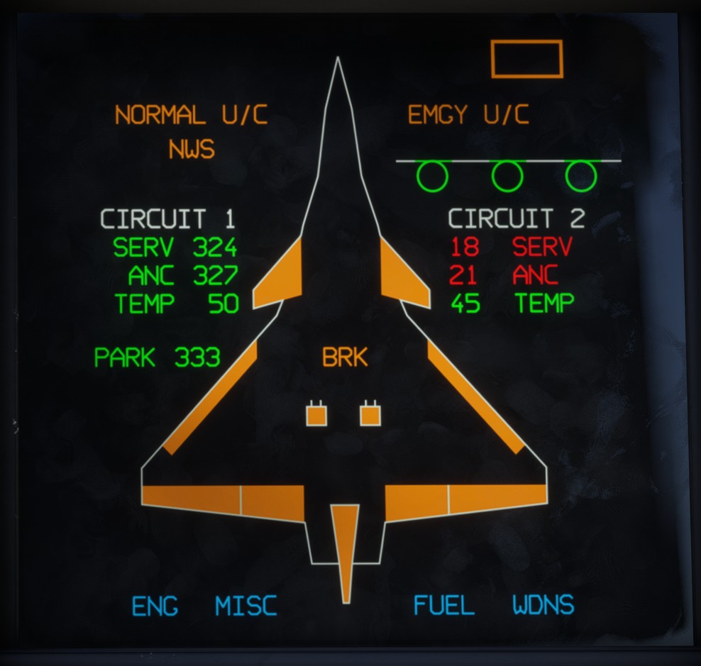
Each indication changes colour when it moves outside its normal operating range:
| Reading | Amber | Red |
|---|---|---|
| Pressure | < 150 bar | < 100 bar |
| Temperature | > 90 °C | > 120 °C |
BRK indicates the availability of the braking system and is displayed in green when available.
PARK indicates the parking brake accumulator pressure. This dedicated accumulator maintains braking pressure when the main hydraulic system is unavailable.
Flight control surfaces
The aircraft silhouette indicates the hydraulic status of each flight control surface: elevons, canards, rudder and slats.
Each surface is powered by both hydraulic circuits. Its indication turns amber when one circuit is unavailable and red when both circuits are unavailable.
Landing gear
NORMAL U/C, NWS and EMGY U/C respectively indicate the availability of the normal landing gear system, nose-wheel steering and emergency landing gear extension system.
In the upper-right corner, each landing gear leg is represented by a circle, which turns green when the gear is down and locked. Each landing gear door is represented according to its current position and turns green when fully closed.
